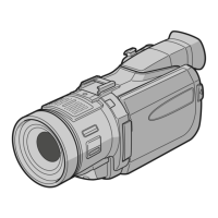
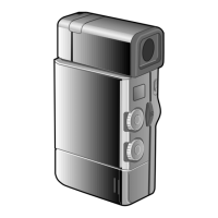
1-10
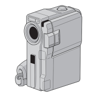
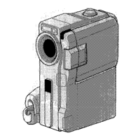
Fig. 1-6-1
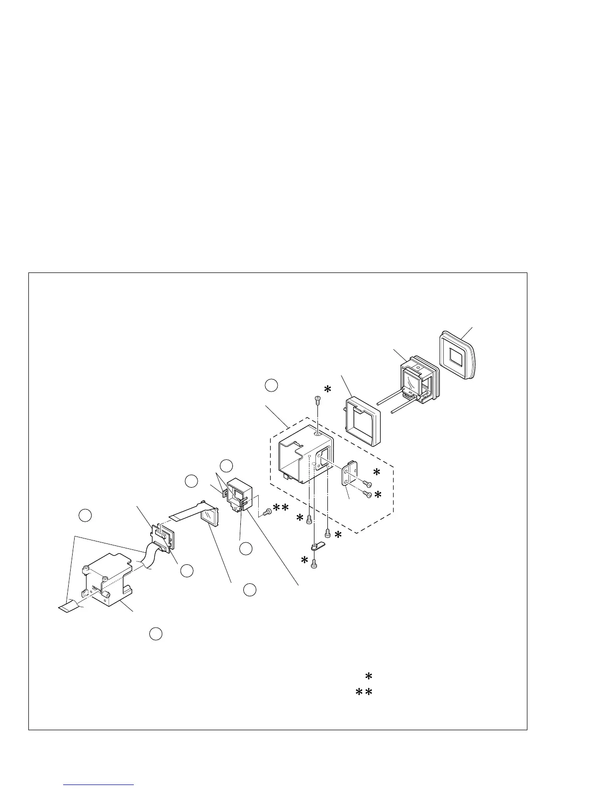
1.6 DISASSEMBLY OF 9 E VF ASSEMBLY
1.6.1 9E VF assembly
Note
9
a:
When disassembling the E VF assembly, remove
the frame (VF) from the case/cap assembly de-
pending on the situation.
Note
9
b:
Be very careful not to get the inside of the VF
soiled or dusty during and after disassembling the
E VF assembly.
Note
9
c:
After the screw having the loose-proof tip was
once removed from the E VF assembly, don’t re-
use it.
1. Remove the eyecup and pull out the guide (VF).
2. Draw the frame (VF) out of the case assembly.
<Case assembly>
3. Remove the screw (1) first and then lever (VF).
4. Remove the three screws (2-4) and draw out the eye-
piece sub assembly.
<Frame (VF)>
5. Remove the screw (5) first and then LCD module/holder
(LCD).
Note
9
d:
Pay heed to the FFC not to damage it during the
removing work.
6. Get the two hooks (L9a, L9b) disengaged and then re-
move the holder (LCD)
Note
9
e:
Carefully proceed with the above-mentioned work
not to damage any part.
7. Disconnect the connector (CN9a) and remove the LCD
module.
Note
9
f:
Pay heed the parts not to damage any thing.
7
6
EYE CUP
GUIDE(VF)
CASE/CAP
2
CAP
(VF)
1
3
4
5
HOLDER
(LCD)
LCD MODULE
B/L SUB ASSY
FRAME(VF)
FFC
: 0.069N·m (0.7kgf·cm)
: 0.098N·m (1.0kgf·cm)
EYE PIECE
SUB ASSY
NOTE e
9
(L b)
9
(L a)
9
CN a
9
NOTE
f
9
NOTE a
9
NOTE d
9
NOTE a
9
 Loading...