1-3
STEP
No.
PART
Fig.No.
POINT NOTE
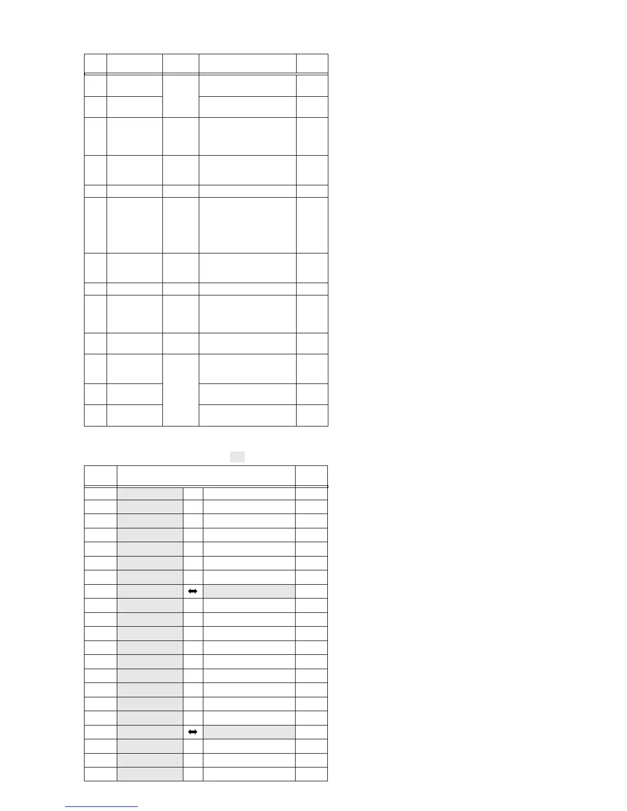
1.3.2 Disassembly method
Table 1-3-2
NOTE
2
:
Beware of electrical shock due to the capacitor during work.
(GR-DVM75U ONLY)
NOTE
3
a:
When disassembling the Front Cover Assembly, remove
the screws, pull out the studs and free the grip belt.
NOTE
3
b:
When attaching the assembly, make sure that the strobe
block fits properly into the frame.
(GR-DVM75U ONLY)
NOTE
4
a:
Remove the Upper Case Assembly before removing the
Monitor Assembly
5
.
NOTE
4
b:
Take care not to damage the parts (battery terminals).
NOTE
4
c:
Take care not to damage the parts (spring).
NOTE
5
:
Refer to Fig. 1-4-1 for the disassembly method.
NOTE
6
a:
Remove the board assemblies (Main/MDA) and Mecha-
nism Assembly together.
NOTE
6
b:
When removing, take care not to disconnect the wire
or damage any of the parts.
NOTE
6
c:
When attaching, be careful of the board attaching position.
NOTE
7
a:
Remove the OP Block Assembly together with the
Strobe Assembly. Beware of electrical shock due to the
capacitor during work.
(GR-DVM75U ONLY)
NOTE
7
b:
When removing, take care not to disconnect the wire
or damage any of the parts.
NOTE
7
c:
Refer to Fig. 1-5-1 for the disassembly method.
NOTE
8
:
Beware of electrical shock due to the capacitor during work.
(GR-DVM75U ONLY)
NOTE
9
a:
When removing, be careful with the FPC (for the Deck
Operation Assembly) attached inside the E.VF Assem-
bly.
Remove the FPC by unplugging it from the connector
and then taking the FPC out together with the E. VF or
by peeling it carefully so that the double-sided adhesive
can be reused later.
NOTE
9
b:
When removing or attaching, take care not to damage
any parts.
Particularly, when attaching the switch, always pull out
the E.VF Assembly to avoid it from damaging the switch.
NOTE
9
c:
When attaching, be careful with the wire treatment.
NOTE
9
d:
Refer to Fig. 1-6-1 for the disassembly method.
NOTE
0
a:
When attaching or removing, take care not to damage
any parts.
Attach the slide switch at the position of the DSC
switch (VIDEO side).
(GR-DVM75U ONLY)
NOTE
0
b:
When attaching, take care with the wire treatment.
This note does not apply when the E.VF Assembly and
FPC have been removed together as shown in Fig. 1-3-
8.
NOTE
!
a:
When unplugging the connector
!
d, be careful with the
handling of the FPC connected to it.
NOTE
!
b:
Connector
!
e is located inside the circuit board, so it
should be the last item to be removed.
NOTE
!
c,
@
:
When attaching, pay heed to the FPC treatment.
Mount the FPC so that it is caught between the Mecha-
nism Assembly and the Main Board Assembly.
CONN.
No.
Pin No.
CONNECTOR
Table 1-3-3
Note:
Remove the parts marked in .
1
a DECK OPE ASSY - ⇔ AUDIO VF CN803 6
2
a AUDIO VF CN804 ←→ MIC UNIT - 4
3
a JACK CN901 ⇔ MAIN CN103 18
4
a MDA CN207 ⇔ SUB OPE ASSY - 7
4
b MAIN CN104 ←→ W/B - 3
4
c MAIN CN106 ⇔ MONITOR CN761 45/39
4
d MAIN CN112 ⇔ J.BOX/MENU - 16
6
a MAIN CN101 AUDIO CN801 80
6
b MAIN CN107 ⇔ CCD - 20
6
c MAIN CN109 ⇔ STROBE - 12
6
d MDA CN205 ⇔ OP BLOCK ASSY - 24
6
e MAIN CN208 ⇔ JUNCTION CN601 20
7
a AUDIO CN805 ⇔ E VF ASSY - 16
9
b AUDIO CN803 ⇔ FPC - 6
!
a MDA CN202 ⇔ DRUM MOTOR - 11
!
b MDA CN201 ⇔ LOADING MOTOR - 6
!
c MDA CN203 ⇔ CAPSTAN MOTOR - 18
!
d MAIN CN102 MDA CN206 80
!
e MDA CN204 ⇔ SENSOR - 15
@a MAIN CN110 ⇔ HEAD - 8
@b MAIN CN111 ⇔ ROTARY ENCODER - 6
1
DECK OPE ASSY Fig.1-3-1 2(S1), (L1) —
聽CN 1a
2
MIC UNIT 2(S2), 2(L2) NOTE2
聽CN 2a
3
FRONT COVER Fig.1-3-2 COVER(DV), (S3a), 3(S3b) NOTE3a
ASSY 2(S3c), (S3d), STUD(HOOK) NOTE3b
(L3)
聽CN 3a
4
UPPER CASE ASSY
Fig.1-3-3 (S4a), 2(L4),
LOCK(MONITOR)
NOTE4a
(Inc.MONITOR (S4b), (S4c), (S4d), 2(S4e) NOTE4b
ASSY) 聽CN 4a, 4b, 4c, 4d NOTE4c
5
MONITOR ASSY Fig.1-3-4 (S5a),(S5b) NOTE5
6
LOWER CASE ASSY
Fig.1-3-5 聽CN 6a, 6b,6c, 6d, 6e NOTE6a
(
Inc.OP BLOCK ASSY
(S6a), 4(S6b) NOTE6b
/STROBE ASSY NOTE6c
/E. VF ASSY
/AUDIO BOARD
ASSY)
7
OP BLOCK ASSY Fig.1-3-6 2(S7),2(L7) NOTE7a
NOTE7b
NOTE7c
8
STROBE ASSY Fig.1-3-7 (S8), GR-DVM75U ONLY NOTE8
9
E.VF ASSY Fig.1-3-8 聽CN 9a, (9b) NOTE9a
(S9), 2(L9) NOTE9b
NOTE9c
NOTE9d
0
AUDIO BOARD ASSY
Fig.1-3-9 SPACER,(S0a),3(S0b),(L0a) NOTE0a
(L0b),BRACKET(TOP) NOTE0b
!
MDA BOARD ASSY
Fig.1-3-10 聽CN !a, !b, !c, (S!) NOTE!a
CN !d, !e NOTE!b
NOTE!c
@
MAIN BOARD ASSY
(S@a), (L@), SHIELD PLATE NOTE@
聽CN @a, @b, (S@b)
#
MECHANISM ASSY
(S#a), 2(S#b), 2(L#) —
BRACKET(MECHA)
 Loading...