2-15
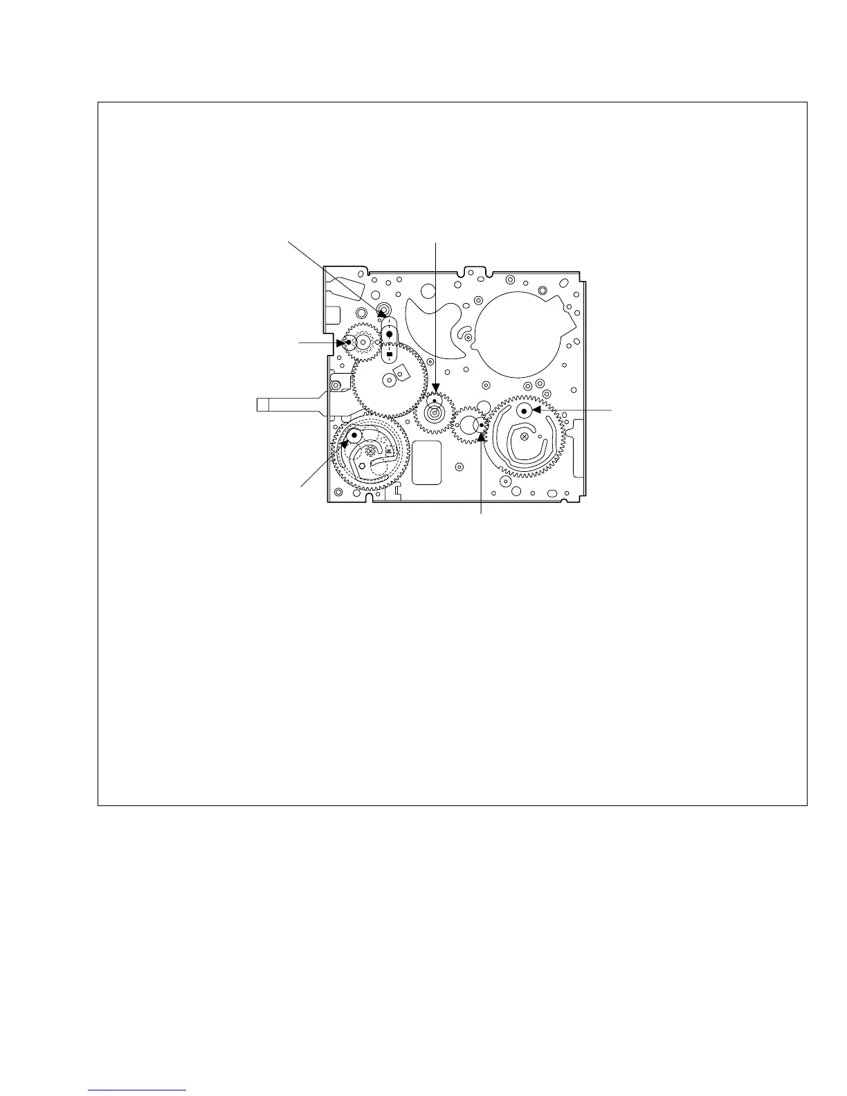
2.5 CHECKUP AND ADJUSTMENT OF MECHANISM PHASE
Fig. 2-5-1
<Rotary encoder>
Set the “■” of the rotary
part at the tapped hole
as shown in the figure.
<Worm wheel> (Note 2)
Set the worm wheel so
that its locating hole
meets the hole on the
main deck assembly.
<Main cam gear
/Brake control plate>
After fitting the main cam\
gear and brake control plat
together,set them together
so that their locating holes
meet the hole on the main \
deck assembly.
<Connect gear 2> (Note 2)
Set the connect gear 2 so
that its locating hole meets
the hole on the main deck
assembly.
<Sub cam gear>
Set the sub cam gear
so that its locating hole
meets the hole on the
main deck assembly.
This state represents
that the mechanism is
in the EJECT mode,
which is the “mechanism
assembly mode”.
<Connect gear> (Note 2)
Set the connect gear so
that its locating hole meets
the hole on the main deck
assembly.
Note 1
Note 1:
Since the connect gear 2 is tightly fixed to the main deck
by caulking, adjust its phase with the connect gear and
sub cam gear.
Note 2:
The part that needs phase adjustment by the hole on the main
deck assembly must exactly be set as the specified phase.
There is a fear that some part is installed in a wrong phase
because assembling of the mechanism is automated. If so,
set every part in the correct phase whenever the mechanism
is reassembled.
 Loading...