I(D-A77
A/B/C/E/J/U
Step
5
6
7
8
Item
Adjusting
recording
level
Checking
record/
playback
signal
distortion
Checking
signal
to
noise ratio
in recor-
ding/play-
back
Checking
erasing
coefficient
Adjustment
1.
Apply
a 1 kHz,
approx.
-10dBs
signal
to
the LINE IN terminals.
Ad-
just
the recording level controls
until the signal is available
at
- 8dBs
at
the LINE
OUT
terminals.
2.
After
checking
to
see
if
the
VU
meters
point
to
0,
record
the
signal
applied
to
both
left
and
right
chan-
nels using a normal tape.
3.
Play back the recorded part.
Perform the recording signal ad-
justment
with
VR501 and VR601
so
that
the
VU
meters
deflect
to
O.
1. Record a 1 kHz signal so
that
OUT-
PUT level become -
8dBs
and VU
meters
deflect
to
O.
2. Play back the recorded part. Check
the
output
with
a
distortion
meter
to
see if
the
value
conforms
to
the
standard value.
1. Record a 1 kHz, OVU signal.
Stop
the
input
by
disconnecting
from
the terminal
to
perform
non-
signal recording.
2.
Play back
the
recorded part.
Measure the OVU recording
output
and the non-signal recording
out-
put
for
comparison using an elec-
tronic
voltmeter.
Check
to
see
if
the
value
conforms
to
the standard value.
1.
Apply
a 1 kHz signal
to
the
LINE
IN
terminals.
Adjust
the recording level controls
until the VU meters
deflect
to
O.
2.
Perform recording
with
the signal
enhanced
by
20dB.
3.
Erase a part
of
the
recording.
4.
Measure the
output
difference
bet-
ween
the erased
part
and non-
erased part
to
compare
with
an
electronic
voltmeter.
Adjusting Standard
point value
VR501
0 VU
601
Normal tape:
Less
than
2.5%
Cr02
tape:
Less
than
3%
Metal
tape
Less
than
2%
Normal tape:
More
than
42dB
Chrome tape:
More
than
42dB
More
than
65dB
Remarks
The level
difference
between
left
and
right
channels
for
normal tape,
chrome
tape and metal
tape
should
be less
than
1 dB
(1
VU). Perform the
adjustment
using a normal tape,
level difference
between
recording
and playback
for
Cr02
and metal
tapes should be less
than
1.
5dB,
and
that
between
left
and
right
channels should also
be
less
than
1 dB.
Be
sure
to
perform this
adjustment
following
bias
current
and recording
level adjustments.
Apply
an
output
(-
72dBs)
to
the
MIC
terminals
with
the
recording
level controls set
to
maximum
so
that
the VU meters
deflect
to
O.
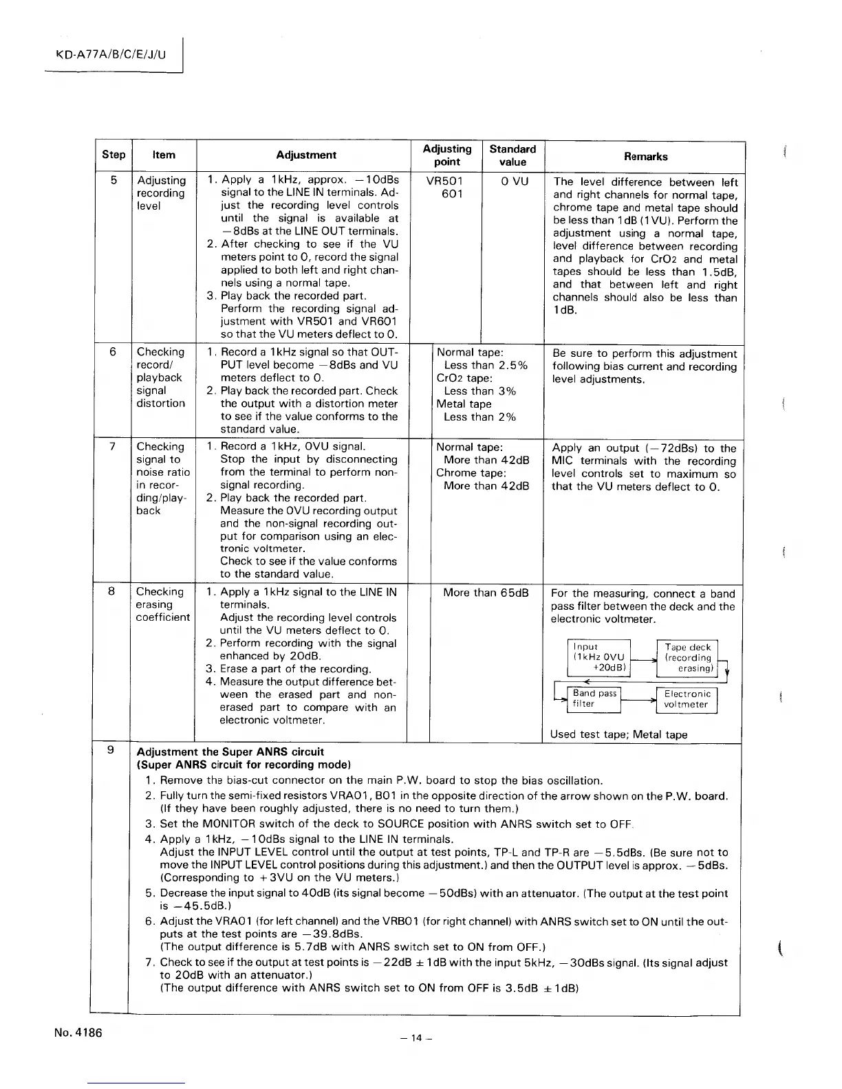
For the measuring,
connect
a band
pass
filter
between
the
deck
and
the
electronic voltmeter.
/
Input
(1
kHz OVU
+20dBi
I r Band pass
I
filter
Tape
deckh
(recording
erasingi
Electronic
I
voltmeter
Used
test
tape; Metal tape
9 Adjustment the Super ANRS circuit
(Super ANRS circuit for recording mode)
1.
Remove
the
bias-cut
connector
on
the
main P.W. board
to
stop
the
bias
oscillation.
2.
Fully
turn
the semi-fixed resistors
VRA01,
B01 in
the
opposite
direction
of
the
arrow
shown
on
the
P.W.
board.
(If
they
have
been
roughly
adjusted,
there
is
no
need
to
turn
them.)
3.
Set
the
MONITOR
switch
of
the
deck
to
SOURCE
position
with
ANRS
switch
set
to
OFF.
4.
Apply
a 1 kHz,
-1
OdBs signal
to
the
LINE
IN
terminals.
Adjust
the
INPUT LEVEL
control
until
the
output
at
test
points,
TP-L and TP-R are
-5.5dBs.
(Be sure
not
to
move
the INPUT LEVEL
control
positions
during this adjustment.) and
then
the
OUTPUT
level is
approx.
- 5dBs.
(Corresponding
to
+
3VU
on
the
VU
meters.)
5. Decrease the
input
signal
to
40dB
(its signal
become
-
50dBs)
with
an
attenuator.
(The
output
at
the
test
point
is
-45.5dB.)
6.
Adjust
the
VRA01
(for
left
channel) and
the
VRB01 (for right channel)
with
ANRS
switch
set
to
ON
until
the
out-
puts
at
the
test
points
are
-39.8dBs.
(The
output
difference
is
5.7dB
with
ANRS
switch
set
to
ON
from
OFF.)
7. Check
to
see
if
the
output
at
test
points
is -
22dB
± 1 dB
with
the
input
5kHz,
-
30dBs
signal. (Its signal
adjust
to
20dB
with
an
attenuator.)
(The
output
difference
with
ANRS
switch
set
to
ON
from
OFF is
3.5dB
± 1 dB)
-14
-
 Loading...