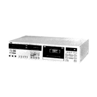
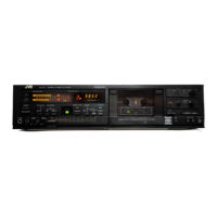
KD-An
A/B/C/E/J/U
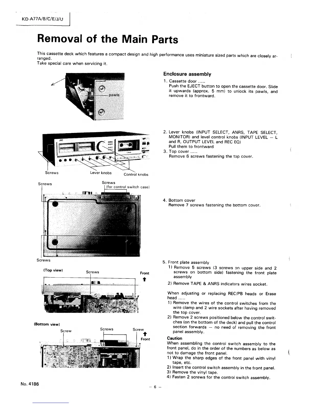
Removal of the Main Parts
This cassette deck
which
features a
compact
design and high performance uses miniature sized parts
which
are closely ar-
ranged.
Take special care
when
servicing it.
.11
Q
~
~--~.
~~~;;;;;:;;.;...f='.
Lever
knobs
Screws
(Top
view)
Screws
(Bottom
view)
Screw
Screws
Screw
l'
Enclosure assembly
1 . Cassette door
.....
Push
the
EJECT
button
to
open
the
cassette door. Slide
it
upwards
(approx. 5 mm)
to
unlock
its
pawls,
and
remove
it
to
frontward.
2.
Lever knobs (INPUT SELECT, ANRS, TAPE SELECT,
MONITOR) and level control knobs (INPUT LEVEL - L
and
R,
OUTPUT LEVEL and
REC
EQ)
Pull
them
to
frontward
3.
Top cover
.....
Remove 6
screws
fastening the
top
cover.
4.
Bottom
cover
Remove
7
screws
fastening the
bottom
cover.
5. Front plate assembly
1) Remove 5
screws
(3
screws
on upper side and 2
screws
on
bottom
side) fastening the
front
plate
assembly
2)
Remove TAPE & ANRS indicators wires
socket.
When adjusting or replacing REC/PB heads or Erase
head .....
1)
Remove
the
wires
of
the
control
switches
from
the
wire clamp and 2
wire
sockets
after
having removed
the top
cover.
2) Remove 2
screws
positioned
below
the
control
swit-
ches (on
the
bottom
of
the deck) and pull
the
control
section
forwards
- no need
of
removing
the
front
panel assembly.
Front
Caution
No.
4186
- 6 -
When
assembling
the
control
switch
assembly
to
the
front
panel,
do
in
the
order
of
the numbers as
below
as
not
to
damage
the
front
panel.
1 ) Wrap
the
sharp edges
of
the
front
panel
with
vinyl
tape, etc.
2)
Insert
the
control
switch
assembly in the
front
panel.
3)
Remove
the
vinyl
tape.
4) Fasten 2
screws
for
the
control
switch
assembly.
 Loading...