3
PRECAUTIONS on power supply and speaker
connections:
• DO NOT connect the speaker leads of the power cord to the car
battery; otherwise, the receiver will be seriously damaged.
• BEFORE connecting the speaker leads of the power cord to the speakers,
check the speaker wiring in your car.
ྑກ֝ಚᑶወોሉٍิො!
• ˞ˢӖಚᑶወዘሉોᏄોгྑЗèѵ۲͵ጆઆᘸࡍ๒ᖣê
• ϚӕಙᑵለᏃвಙᑵ˃ۮçᐓފԆԾʕڄಙᑵለཔé
¢ÈÕ§«√√–«—ß”À√—∫°“√µËÕ·À≈Ë߮˓¬°”≈—ß·≈–≈”‚æß:
• լ˓µËÕ“¬µ–°—Ë«‡§‡∫‘≈°”≈—ߢÕß≈”‚æ߇¢È“°—∫·∫µ‡µÕ√’Ë√∂¬πµÏ ¡‘©–π—Èπ ™ÿ¥ª√–
°Õ∫®–‰¥È√—∫§«“¡‡’¬À“¬¡“°
• °ËÕπ∑’Ë®–µËÕ“¬µ–°—Ë«‡§‡∫‘≈°”≈—ߢÕß≈”‚æ߇¢È“°—∫≈”‚æß
„Àȵ√«®Õ∫°“√‡¥‘𓬉ø≈”‚æß„π√∂¢Õߧÿ≥„Àȇ√’¬∫√ÈÕ¬‡’¬°ËÕπ
A
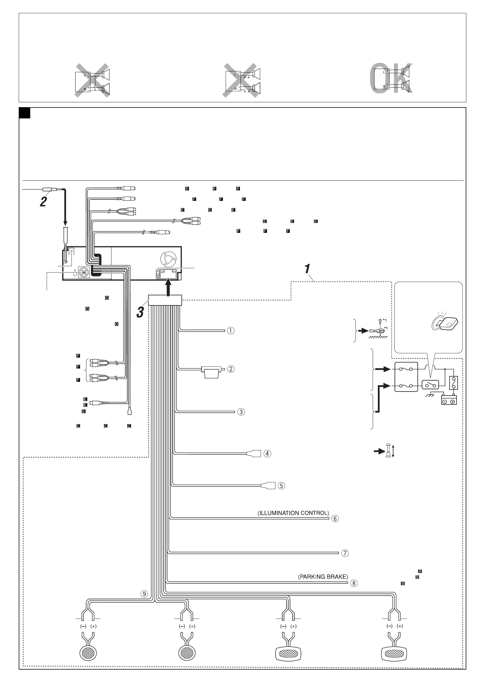
Typical Connections / նܔڅોሉ٘ / °“√‡™◊ËÕ¡µËÕ·∫∫ª°µ
Before connecting: Check the wiring in the vehicle carefully. Incorrect
connection may cause serious damage to this receiver.
The leads of the power cord and those of the connector from the car body
may be different in color.
1 Connect the colored leads of the power cord in the order
specified in the illustration below.
2 Connect the antenna cord.
3 Finally connect the wiring harness to the receiver.
ોሉۯ!அᐓފԆԾ˖ڄለཔéʿᇧڄለࠓʹጅᘷࡌ๑ᖢé
ྐʍለڄ˺ለ֜ԾԽڄ˺ለϚᖄиʕЉʿψé
1 ՜ຖʓ࿌Ε˃ЎҺྐለڄᖄиለé
2 અ˭ለڄྐለ৹գé
3 ఛ݈çӕለӧڄᏃϚʹጅʕé
°ËÕ•∑”°“•‡™•ËÕ¡µËÕ: µ•«®†Õ•°“•‡¥‘•†“¬‰ø„•••¬•µÏլ˓ߕ–¡—¥•–«—լ˓„ÀȺ‘¥æ
•“¥„•°“•‡™•ËÕ¡µËÕ™ÿ¥ª•–°Õ•™ÿ¥•’
°“•‡™•ËÕ¡µËÕº‘¥æ•“¥Õ“®∑”„Àȇ°‘¥§«“¡‡’¬À“¬•È“¬·•ß°—•™ÿ¥ª•–
°Õ••’ȉ¥È“•µ–°—Ë«¢Õ߆“¬‰ø ·•–¢ÕßÕÿª°••ÏµËÕ‡™•ËÕ¡®“°µ—«• ß••Õ“®¡’
∑’ˉ¡Ë‡À¡•Õ•°—•
1 µËÕ“¬‰ø’µ“¡≈”¥—∫∑’Ë√–∫ÿ„π√Ÿª¥È“π≈Ë“ß
2 ‡™◊ËÕ¡µËÕ°—∫“¬Õ“°“»
3 ÿ¥∑È“¬ µËËÕò«π§«∫§ÿ¡°“√‡¥‘𓬉ø‡¢È“°—∫™ÿ¥ª√–°Õ∫™ÿ¥π’È
SUBWOOFER OUT (see diagram / ኌ࿌ڷ / ¥Ÿ·ºπ¿Ÿ¡ )
15 A fuse
15 A ۘᎳീ
ø‘«Ï¢π“¥ 15 A
Rear ground terminal
ʹጅ݈ࠌϙၷʪ
®ÿ¥‡™◊ËÕ¡µËÕ“¬¥‘π¥È“πÀ≈—ß
Line out
(see diagram )
᎔ၷʪ
(ኌ࿌ڷ )
“¬ÕÕ°
(¥Ÿ·ºπ¿Ÿ¡ )
To CD changer, interface adapter for iPod/D.player,
or another external component (see diagram
)
в CD ಗၪጅèiPod/D.player ڄߍࡒቱ
çմ௰༫ኌ࿌ڷ Ą
µËÕ°—∫´’¥’‡™π‡®Õ√Ï Õ‘π‡∑Õ√χøÕ–·¥ª‡µÕ√Ï”À√—∫
iPod/‡§√◊ËÕ߇≈Ëπ D. À√◊ÕÕÿª°√≥Ï¿“¬πÕ° (¥Ÿ·ºπ¿Ÿ¡‘ )
*
1
Not included for this receiver
*
1
ʿ҉Ϛʹጅ˖é
*
1
‰¡Ë‰¥È„ÀÈ¡“°—∫™ÿ¥ª√–°Õ∫π
Ignition switch
ᓭළᘕ
«‘∑™Ï®ÿ¥√–‡∫‘¥
Fuse block
ۘᎳീవ˔
·ºßøî«
White with black stripe
ΎиઘЉ෨иঙ
’¢“«·∂∫¥”
White
Ύи
’¢“«
Gray with black stripe
НиઘЉ෨иঙ
’‡∑“·∂∫¥”
Gray
Ни
’‡∑“
Green with black stripe
ႋиઘЉ෨иঙ
’‡¢’¬«·∂∫¥”
Green
ႋи
’‡¢’¬«
Purple with black stripe
ാиઘЉ෨иঙ
¡Ë«ß·∂∫¥”
Purple
ാи
’¡Ë«ß
Left speaker (rear)
ಙᑵ݈
≈”‚æß´È“¬ (À≈—ß)
Right speaker (rear)
ಙᑵ݈
≈”‚æߢ«“ (À≈—ß)
To metallic body or chassis of the car
вہᚙᝂԆԾנᇟ
µËÕ°—∫‚§√ß‚≈À–À√◊Õ‡™´‘¢Õß√∂¬πµú
To a live terminal in the fuse block connecting to the car battery
(bypassing the ignition switch) (constant 12 V)
вۘᎳീవ˔˖ڄۈᚙၷʪçۘᎳീవ˔ؠԾ༫ྐЖߟ
·ؠཔᓭළᘕݔ׆ 12 V
µµËÕ°—∫¢—È«∑’Ë¡’°√–·‰øøÈ“„π·ºßø‘«Ï ´÷ËßµËÕ°—∫·∫µ‡µÕ√’Ë√∂¬πµ
(‚¥¬‰¡ËµÈÕß„™È«‘∑™Ï®ÿ¥√–‡∫‘¥) (12 ‚«≈∑ϧß∑’Ë)
To an accessory terminal in the fuse block
вۘᎳീవ˔˖ڄۈᚙၷʪ
µËÕ°—∫¢—È«Ë«πª√–°Õ∫„π·ºßø‘«
To automatic antenna if any (250 mA max.)
вб˭ለࠜЉ༫ఛʨ250 mA
‡“Õ“°“»‰øøÈ“Õ—µ‚π¡—µ‘ À“°¡’ (¢π“¥Ÿß¸¥ 250 mA)
To car light control switch
вԆԾԾጜվළᘕ
«‘µ´Ï§«∫§ÿ¡‰ø¢Õß√∂¬πµ√Ï
To cellular phone system
вޟྐ༼Ԧ
µËÕ°—∫‚∑√»—æ∑χ§≈◊ËÕπ∑
To parking brake (see diagram )
в˾۫Ծለ(ኌ࿌ڷ
)
µËÕ°—∫‡∫√°¡◊Õ (¥Ÿ·ºπ¿Ÿ¡ )
Black
෨и
’¥”
Yellow *
2
෦и *
2
’‡À≈◊Õß *
2
Red
߹и
’·¥ß
Blue with white stripe
ᕇиઘЉΎиঙ
πÈ”‡ß‘π≈“¬¢“«
Orange with white stripe
ዻиઘЉΎиঙ
’È¡·∂∫¢“«
Brown
ሶи
’πÈ”µ“≈
Light green
ଠႋи
’‡¢’¬«ÕËÕπ
LINE IN (see diagram / ኌ࿌ڷ / ¥Ÿ·ºπ¿Ÿ¡ )
2nd AUDIO OUT (see diagram
/ ኌ࿌ڷ / ¥Ÿ·ºπ¿Ÿ¡ )
VIDEO IN (see diagram / ኌ࿌ڷ / ¥Ÿ·ºπ¿Ÿ¡ )
REVERSE GEAR SIGNAL
(see diagram
/ ኌ࿌ڷ / ¥Ÿ·ºπ¿Ÿ¡ )
VIDEO OUT
(see diagram
ኌ࿌ڷ
¥Ÿ·ºπ¿Ÿ¡ )
Blue
ᕇи
»’øÈ“
To the remote lead of other equipment (200 mA max.)
вɾށࡖᛏకڄჲለఛʨ 200 mA
µËÕ‡¢È“°—∫Õª°√≥ÏÕË◊π (¢π“¥Ÿß¸¥ 200 mA)
CENTER OUT (see diagram / ኌ࿌ڷ / ¥Ÿ·ºπ¿Ÿ¡ )
*
2
Before checking the operation of this receiver prior to
installation, this lead must be connected, otherwise power
cannot be turned on.
*
2
ʹጅ͵ϯ༫çනмʳѕٶٜᐓފ˃ۮç
ෝӕለʕçѴ۱ʿළ૧ྐé
*
2
°ËÕπ°“√µ√«®Õ∫°“√∑”ß“π¢Õß™ÿ¥ª√–°Õ∫π’È°ËÕπ∑’Ë®–µ‘¥µ—Èß
µÈÕßµËÕ“¬µ–°—Ë«π’È°ËÕπ ¡‘©–π—Èπ®–‰¡Ë“¡“√∂‡ª‘¥‡§√◊ËÕ߉¥È
Left speaker (front)
ಙᑵۮ
≈”‚æß´È“¬ (ÀπÈ“)
Right speaker (front)
ಙᑵۮ
≈”‚æߢ«“ (ÀπÈ“)
ˁ
Instal1-3_KD-AVX2[U].indd 3Instal1-3_KD-AVX2[U].indd 3 2/8/06 6:40:30 PM2/8/06 6:40:30 PM
 Loading...