EasyManuals Logo
Home>JVC>Car Receiver>KD-G401

JVC KD-G401 Service Manual

JVC KD-G401
53 pages
To Next Page IconTo Next Page
To Previous Page IconTo Previous Page
Page #24 background imageLoading...
Page #24 background image
1-24 (No.MA051)
SECTION 4
ADJUSTMENT
4.1 Adjustment method
Test instruments required for adjustment
(1) Digital oscilloscope (100MHz)
(2) AM Standard signal generator
(3) FM Standard signal generator
(4) Stereo modulator
(5) Electric voltmeter
(6) Digital tester
(7) Tracking offset meter
(8) Test Disc JVC :CTS-1000
(9) Extension cable for check
EXTSH002-22P × 1
Standard volume position
Balance and Bass &Treble volume : lndication"0"
Loudness : OFF
Standard measuring conditions
Dummy load
Exclusive dummy load should be used for AM,and FM. For FM
dummy load,there is a loss of 6dB between SSG output and
antenna input.The loss of 6dB need not be considered since
direct reading of figures are applied in this working standard.
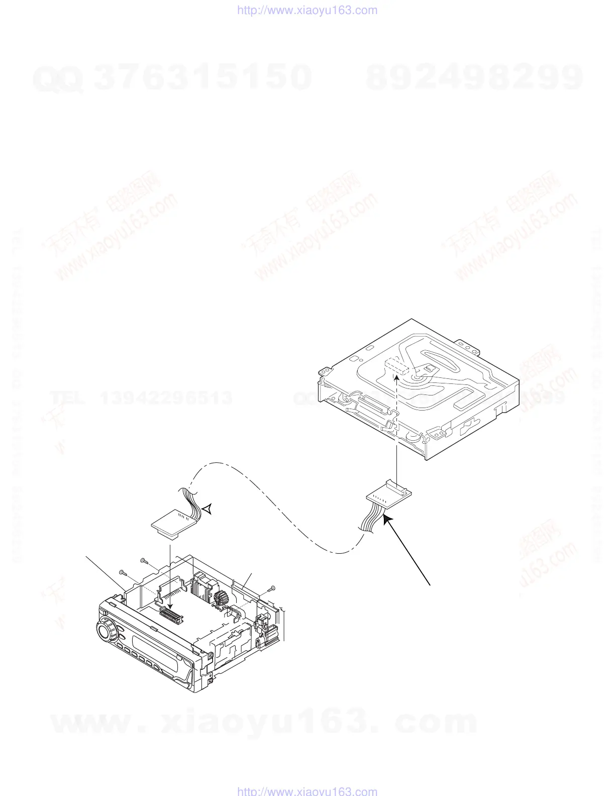
How to connect the extension cable for adjusting
Caution:
Be sure to attach the heat sink and rear bracket onto the power amplifier IC and regulator IC respectively, before supply the power.
If voltage is applied without attaching these parts, the power amplifier IC and regulator IC will be destroyed by heat.
Power supply voltage DC14.4V(11 to 16V)
Load impedance 20K(2 Speakers connection)
Output Level Line out 2.0V (Vol. MAX)
Heat sink
Rear bracket
Extension cable: EXTSH002-22P
w
w
w
.
x
i
a
o
y
u
1
6
3
.
c
o
m
Q
Q
3
7
6
3
1
5
1
5
0
9
9
2
8
9
4
2
9
8
T
E
L
1
3
9
4
2
2
9
6
5
1
3
9
9
2
8
9
4
2
9
8
0
5
1
5
1
3
6
7
3
Q
Q
TEL 13942296513 QQ 376315150 892498299
http://www.xiaoyu163.com

Other manuals for JVC KD-G401

Questions and Answers:

Question and Answer IconNeed help?

Do you have a question about the JVC KD-G401 and is the answer not in the manual?

JVC KD-G401 Specifications

Audio Amplifier IconAudio Amplifier
maximum power output (front)50 W per channel
maximum power output (rear)50 W per channel
continuous power output (RMS) (front)19 W per channel into 4 Ω, 40 Hz to 20 000 Hz at no more than 0.8% total harmonic distortion
continuous power output (RMS) (rear)19 W per channel into 4 Ω, 40 Hz to 20 000 Hz at no more than 0.8% total harmonic distortion
load impedance4 Ω (4 Ω to 8 Ω allowance)
tone control range (bass)±10 dB at 100 Hz
tone control range (treble)±10 dB at 10 kHz
frequency response40 Hz to 20 000 Hz
signal-to-noise ratio70 dB
line-out level/impedance2.0 V/20 kΩ load (full scale)
output impedance1 kΩ
CD Player IconCD Player
operating voltageDC 14.4 V (11 V to 16 V allowance)
allowable operating temperature0°C to +40°C
dimensions (W × H × D)182 mm × 52 mm × 150 mm
panel size188 mm × 58 mm × 11 mm
mass1.3 kg (excluding accessories)
frequency response5 Hz to 20 000 Hz
dynamic range96 dB
signal-to-noise ratio98 dB
max. bit rate320 Kbps
Tuner IconTuner
frequency range (FM)87.5 MHz to 108.0 MHz
frequency range (AM MW)522 kHz to 1 620 kHz
frequency range (AM LW)144 kHz to 279 kHz
usable sensitivity11.3 dBf (1.0 µV/75 Ω)
50 dB quieting sensitivity16.3 dBf (1.8 µV/75 Ω)
alternate channel selectivity (400 kHz)65 dB
frequency response40 Hz to 15 000 Hz
stereo separation30 dB
capture ratio1.5 dB
sensitivity (MW)20 µV
selectivity (MW)35 dB
sensitivity (LW)50 µV

Related product manuals