(No.MA665<Rev.001>)11/33
SECTION 3
DISASSEMBLY
3.1 Main body
3.1.1 Removing the MAIN PWB (See Fig.1 to 3)
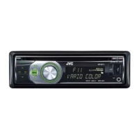
(1) Disengage the 6 hooks, and remove the SUB PANEL
ASS’Y. (See Fig.1)
Fig.1
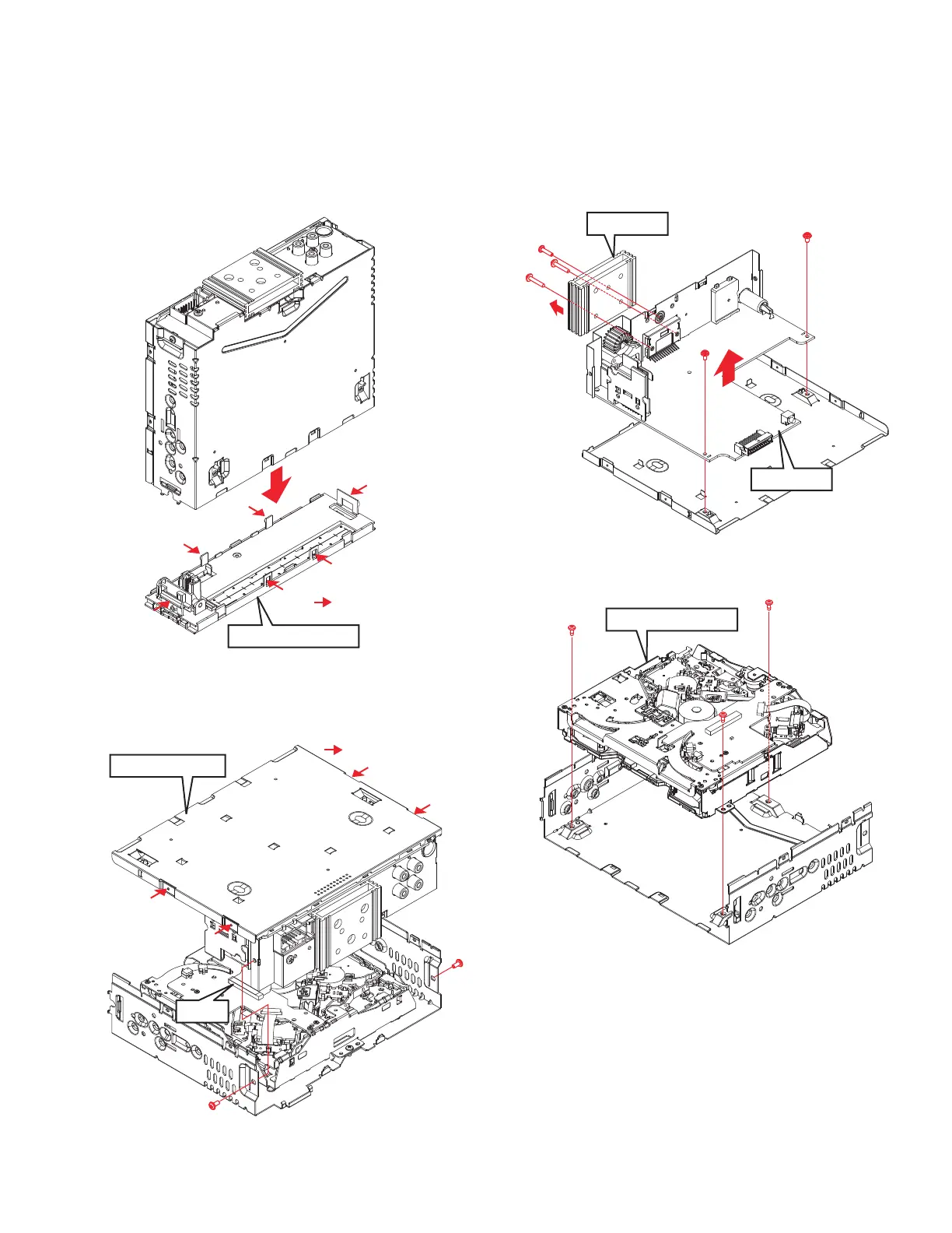
(2) Remove the 2 screws. (See Fig.2)
(3) Disengage the 4 hooks, and remove the BOTTOM PLATE.
(See Fig.2)
(4) Disconnect the FFC wire forn the connector. (See Fig.2)
Fig.2
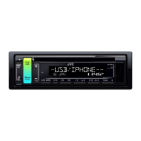
(5) Remove the 2 screws (a), and remove the MAIN PWB.
(See Fig.3)
(6) Remove the 3 screws (b,c), and remove the HEAT SINK.
(See Fig.3)
Fig.3
3.1.2 Removing the CD MECHANISM (See Fig.4)
(1) Remove the 3 screws, and remove the CD MECHANISM.
Fig.4
SUB PANEL ASS'Y
: Hook position
BOTTOM PLATE
: Hook position
CN1
b
b
c
a
a
MAIN PWB
HEAT SINK
CD MECHANISM
 Loading...