1
2
3
4
5
6
7
8
9
10
11
12
13
14
15
16
17
18
19
20
21
22
23
24
25
26
27
28
29
30
31
32
33
34
35
36
SW2
SW3
SW4
REST
LM0
LM1
NC
LCDPWR
VDD
X2
X1
VSS
XT2
XT1
RESET
SW1
BUSINT
PS2
CRUISE
NC
NC
REMOCON
AVDD
AVREF0
VOL1
VOL2
KEY0
KEY1
KEY2
LEVEL
AVSS
NC
NC
AVREF
Detection switch of CD mechanism
Detection switch of CD mechanism
Detection switch of CD mechanism
Reset signal input from CD mechanism
Loading motor control signal output
Loading motor control signal output
Non connect
LCD driver power supply control output H:ON
Power supply terminal
Connecting the crystal oscillator for system main clock
Connecting the crystal oscillator for system main clock
Power supply terminal
Connecting the crystal oscillator for system sub clock
Connecting the crystal oscillator for system sub clock
System reset signal input
Detection switch of CD mechanism
Cut-in input for J-BUS signal
Power save 2, Working together back up by H input, to stop mode
Pulse signal input port for Cruise control
Clock signal input for RDS
RDS data input
Remote control signal input
Power supply terminal
Power supply terminal
Input for rotation volume detection pulse judgment to relation V1
Input for rotation volume detection pulse judgment to relation V2
Key control signal input 0
Key control signal input 1
Key control signal input 2
Signal input port of level meter
Connect to GND
Subwoofer volume control analogue output
Non connect
Power supply terminal
I
I
I
I
O
O
-
O
-
-
-
-
-
-
I
I
I
I
I
-
-
I
-
-
I
I
I
I
I
I
I
I
-
O
O
-
Pin No.
Symbol
I/O
Function
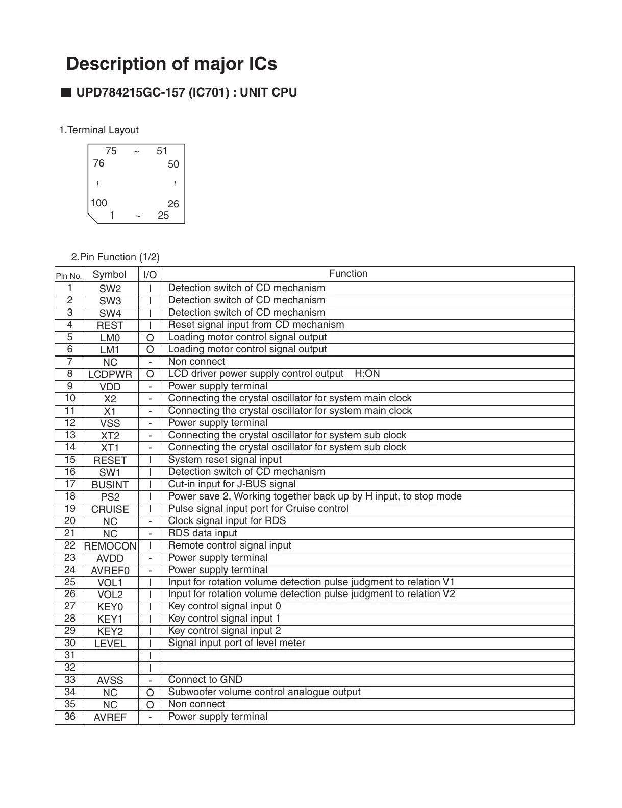
UPD784215GC-157 (IC701) : UNIT CPU
75 ~ 51
1 ~ 25
76
100
50
26
~
~
1.Terminal Layout
2.Pin Function (1/2)
Description of major ICs
 Loading...