(No.MA195)1-3
SECTION 3
DISASSEMBLY
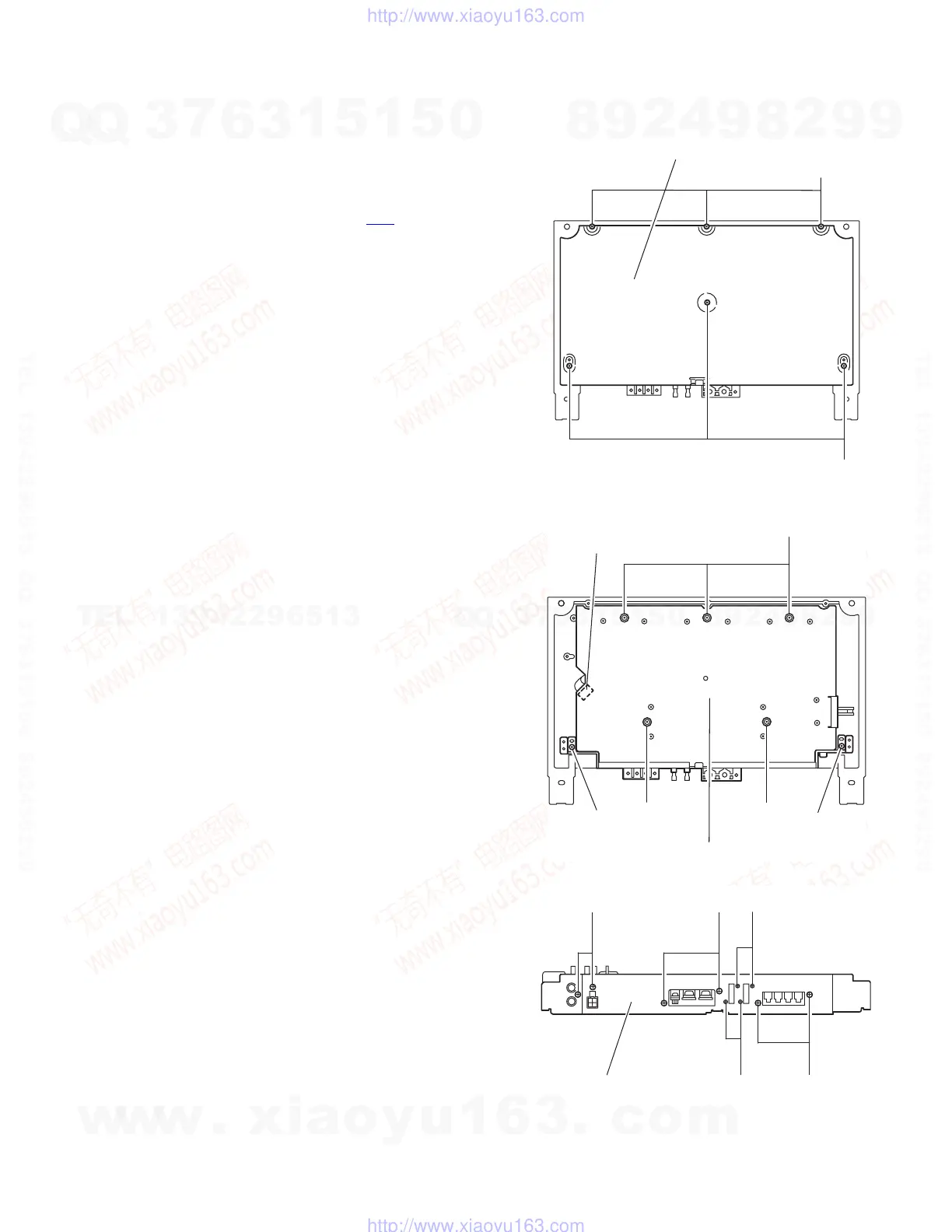
3.1 Main body
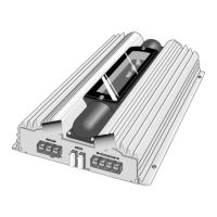
3.1.1 Removing the main board (See Fig.1 to 3)
(1) From the bottom of the body, remove the six screws A at-
taching the cover.
(2) Disconnect the wire from connector CN2
on the main
board.
(3) Remove the five screws B, the two screws D attaching the
main board.
(4) From the front side of the body, remove the six screws E
and the four screws F attaching the cover.
Fig.1
Fig.2
Fig.3
A
A
Cover
B
BB
DD
CN2
Main board
E
E
F
F
E
Rear cover
w
w
w
.
x
i
a
o
y
u
1
6
3
.
c
o
m
Q
Q
3
7
6
3
1
5
1
5
0
9
9
2
8
9
4
2
9
8
T
E
L
1
3
9
4
2
2
9
6
5
1
3
9
9
2
8
9
4
2
9
8
0
5
1
5
1
3
6
7
3
Q
Q
TEL 13942296513 QQ 376315150 892498299
TEL 13942296513 QQ 376315150 892498299
http://www.xiaoyu163.com
http://www.xiaoyu163.com
 Loading...