(No.PA063<Rev.001>)1-3
(11) Products using cathode ray tubes (CRTs)In regard to such
products, the cathode ray tubes themselves, the high volt-
age circuits, and related circuits are specified for compli-
ance with recognized codes pertaining to X-ray emission.
Consequently, when servicing these products, replace the
cathode ray tubes and other parts with only the specified
parts. Under no circumstances attempt to modify these cir-
cuits.Unauthorized modification can increase the high volt-
age value and cause X-ray emission from the cathode ray
tube.
(12) Crimp type wire connector In such cases as when replac-
ing the power transformer in sets where the connections
between the power cord and power trans former primary
lead wires are performed using crimp type connectors, if
replacing the connectors is unavoidable, in order to prevent
safety hazards, perform carefully and precisely according
to the following steps.
• Connector part number:E03830-001
• Required tool: Connector crimping tool of the proper
type which will not damage insulated parts.
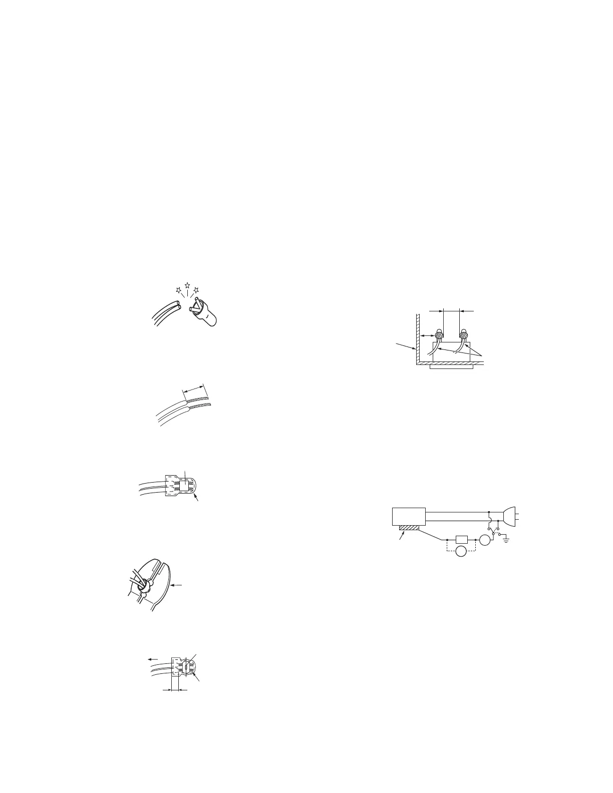
• Replacement procedure
a) Remove the old connector by cutting the wires at a
point close to the connector.Important: Do not re-
use a connector (discard it).
Fig.1-1-3
b) Strip about 15 mm of the insulation from the ends
of the wires. If the wires are stranded, twist the
strands to avoid frayed conductors.
Fig.1-1-4
c) Align the lengths of the wires to be connected. In-
sert the wires fully into the connector.
Fig.1-1-5
d) As shown in Fig.1-1-6, use the crimping tool to
crimp the metal sleeve at the center position. Be
sure to crimp fully to the complete closure of the
tool.
Fig.1-1-6
e) Check the four points noted in Fig.1-1-7.
Fig.1-1-7
1.1.2 SAFETY CHECK AFTER SERVICING
Examine the area surrounding the repaired location for damage
or deterioration. Observe that screws, parts and wires have been
returned to original positions, Afterwards, perform the following
tests and confirm the specified values in order to verify compli-
ance with safety standards.
(1) Insulation resistance test
Confirm the specified insulation resistance or greater be-
tween power cord plug prongs and externally exposed
parts of the set (RF terminals, antenna terminals, video and
audio input and output terminals, microphone jacks, ear-
phone jacks, etc.).See table 1 below.
(2) Dielectric strength test
Confirm specified dielectric strength or greater between
power cord plug prongs and exposed accessible parts of
the set (RF terminals, antenna terminals, video and audio
input and output terminals, microphone jacks, earphone
jacks, etc.). See Fig.1-1-11 below.
(3) Clearance distance
When replacing primary circuit components, confirm spec-
ified clearance distance (d), (d') between soldered termi-
nals, and between terminals and surrounding metallic
parts. See Fig.1-1-11 below.
Fig.1-1-8
(4) Leakage current test
Confirm specified or lower leakage current between earth
ground/power cord plug prongs and externally exposed ac-
cessible parts (RF terminals, antenna terminals, video and
audio input and output terminals, microphone jacks, ear-
phone jacks, etc.).
Measuring Method: (Power ON) Insert load Z between
earth ground/power cord plug prongs and externally ex-
posed accessible parts. Use an AC voltmeter to measure
across both terminals of load Z. See Fig.1-1-9 and follow-
ing Fig.1-1-12.
Fig.1-1-9
cut close to connector
15 mm
Connector
Metal sleeve
1
.2
5
2
.0
5.5
Crimping tool
Not easily pulled free
Crimped at approx. center
of metal sleeve
Conductors extended
Wire insulation recessed
more than 4 mm
Chassis
Power cord
primary wire
d'
d
ab
c
V
A
Externally
exposed
accessible part
Z
 Loading...