1-6
<Disassembly of the main blocks of this set>
Replacement of the fuses and the power IC
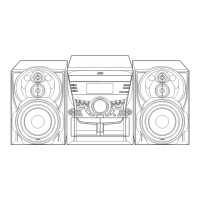
n Replacing the fuses (See Fig.1, Fig.4)
n
Prior to performing the following procedure, remove
the left side BOARD and remove tuner PCB (Fig.4,BB)
1. Replace the fuses inside.
[Caution] Be sure to use fuses with the specified ratings.
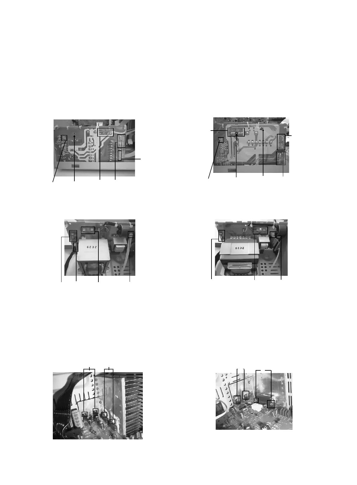
n Replacing the power IC (See Fig.2 to 3)
n
Prior to performing the following procedure, remove
the top cover.
1. Remove the two screws "A" from the heat sinkbetween
the power IC.
2. Remove the solder fixing the power IC.
Fuse (F952)
T1.6AL 250V
FW981
Fuse(F981)
T1AL 250V
CN981
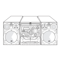
For CA-MXK10R/15R Fig.1(A)
Component SIDE
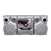
Fuse(F952)
T1.6AL 250V
Fuse (F981)
T2AL 250V
CN981
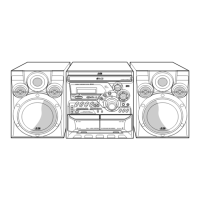
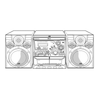
For CA-MXK30R Fig.1(B)
Component SIDE
W
A
For CA-MXK10R/15R Fig.2
w
A
For CA-MXK30R Fig.3
CN981
CAUTION
(don’t remove
the safety sheet
cover )
Fuse(F981)
T1AL 250V
Fuse(F952)
T1.6AL 250V
For CA-MXK10R/15R Fig.1(A)
BOTTOM SIDE
FW981
CN981
CAUTION
(don’t remove
the safety sheet
cover )
Fuse(F952)
Fuse Hole
HOLE
FW951
For CA-MXK30R Fig.1(B)
BOTTOM SIDE
Fuse (F981)
T2AL 250V
 Loading...