(No.MB448)1-7
SECTION 3
DISASSEMBLY
3.1 Main body section
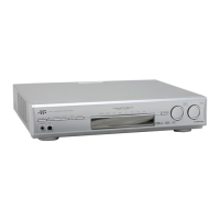
3.1.1 Removing the top cover
(See Figs.1 and 2)
(1) From the both sides of the main body, remove the four
screws A attaching the top cover. (See Fig.1)
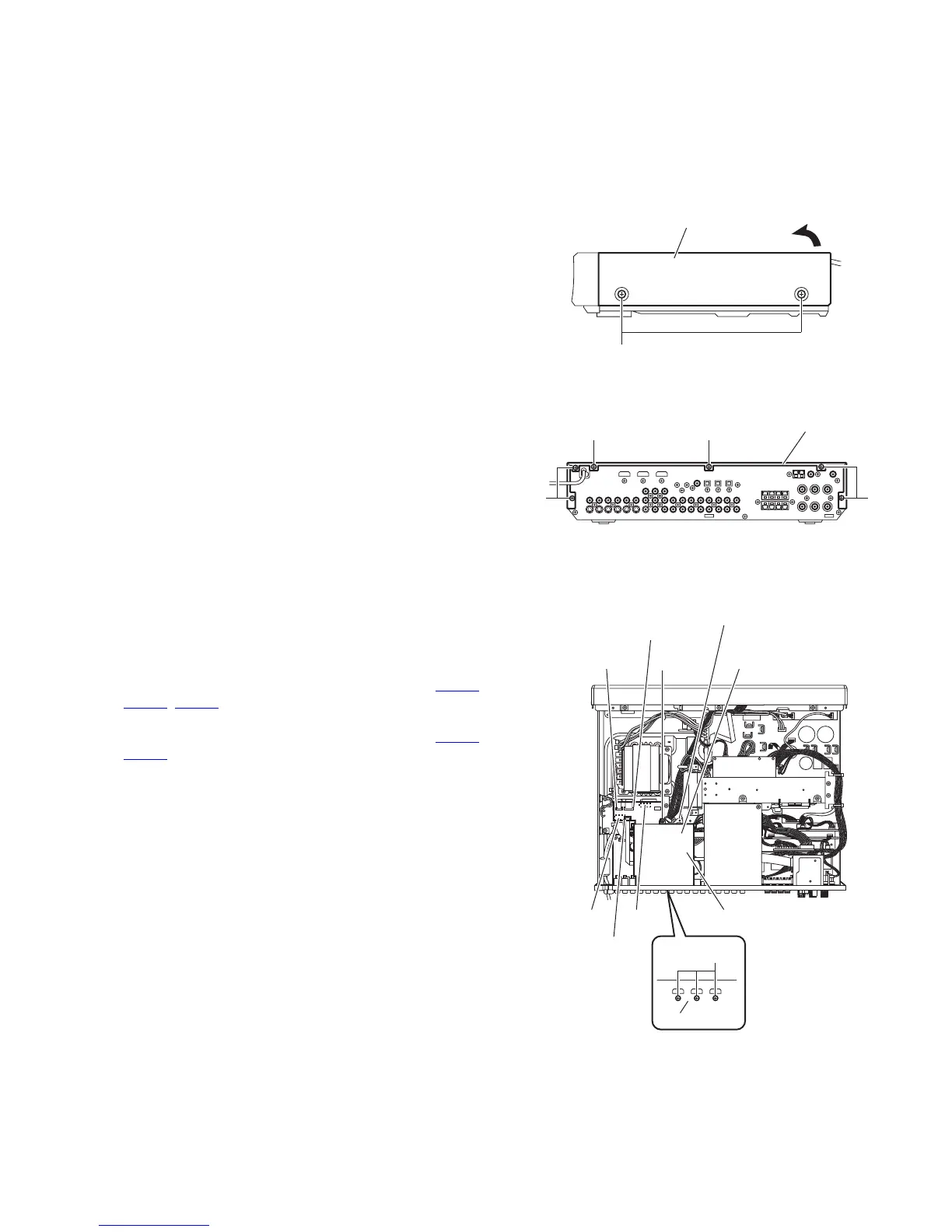
(2) From the back side of the main body, remove the five
screws B and screw C attaching the top cover. (See Fig.2)
(3) Remove the top cover in the direction of the arrow. (See
Fig.1.)
Fig.1
Fig.2
3.1.2 Removing the HDMI board
(See Fig.3)
• Remove the top cover.
(1) From the back side of the main body, remove the three
screws D attaching the HDMI board to the rear panel.
(2) From the top side of the main body, remove the screw E at-
taching the HDMI board to the support bracket.
(3) Disconnect the card wires from the connectors (CN731
,
CN732
, CN762) on the HDMI board.
(4) Take out the HDMI board from the main body and discon-
nect the parallel wires from the connectors (CN771,
CN772
) on the reverse side of the HDMI board.
Reference:
Remove the shield from the HDMI board as required.
Fig.3
A
Top cover
B
Top cover
B B
C
E
D
Shield
CN732
CN731
CN771
CN762
CN772 HDMI board
Rear panel
Support bracket
 Loading...