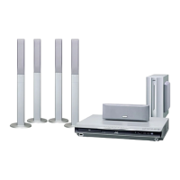
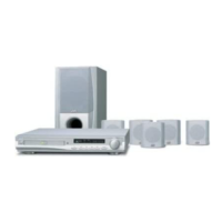
1-14 (No.MB141)
SECTION 5
TROUBLESHOOTING
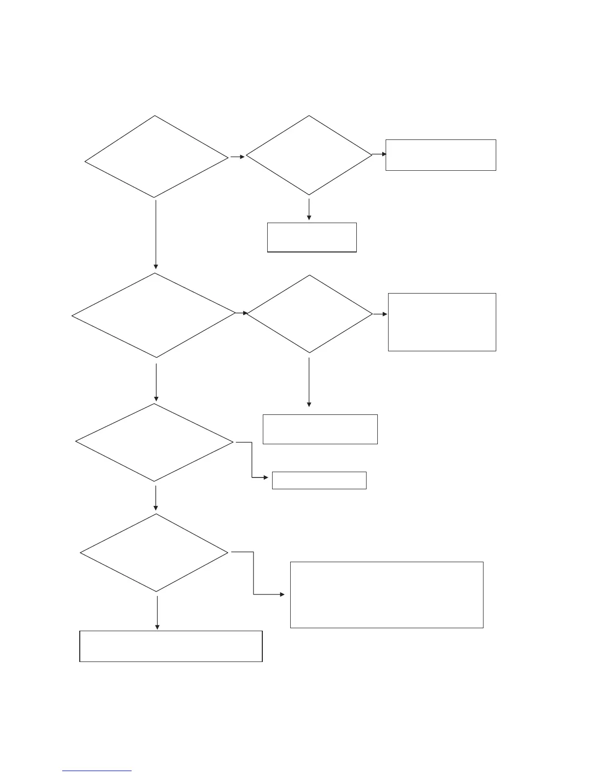
5.1 MAIN
5.1.1 POWER
Check for VCC(5V)
at
FRONT PCB
;pin #17,46,72,90 of UIC1
Check for power-sense(5V)at FRONT PCB
;pin #77 of UIC1
When power on for FRONT PCB
Check for High Voltage(5V) at"M"com
;pin#
74 of UIC1
Check low Voltage(0V)
at
EXPAND IC (M66010)
;pin#32 of UIC500
Check for connector from DSP PCB to FRONT PCB
;VCW7
Check normal Voltage
at
POWER PCB
AZD1 (5.1V, 1/2W)
Check pattern from VCW7
to pin#77 of UIC1
Replace Micom(UIC1)
If High Voltage (5V), check for Circuit protection
Check connector wire Ass'y of power
P/T - MAIN PCB(7P,ACW3)
MAIN PCB (8P,PW3)
Replace AZD1
Check resistant from GND
to pin #77 of MICOM(UIC1)
if the short(0 ohm),to replace
Micom(UIC1)
Check for Input voltage
at
POWER PCB
;AIC1(7805)
Replace
AIC1
Check for circuit at Sub Trans
;PBD2, PT1, AFS3(Fuse)
NO
NO
NO
NO
NO
YES
YES
YES
YES
YES
YES
NO
 Loading...