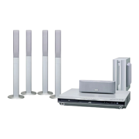
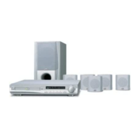
1-16 (No.MB141)
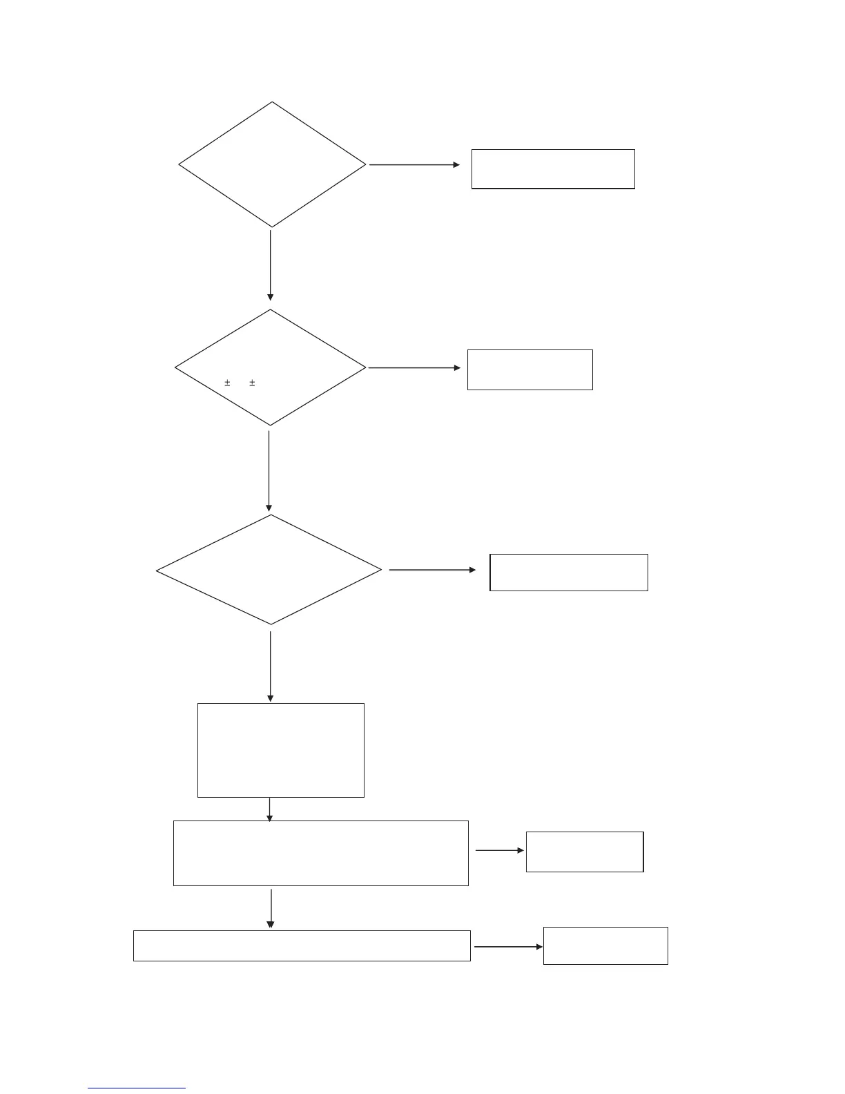
5.1.3 Protection(When High Voltage at Protectiion port)
5.1.3.1 In this case "LOW" for, Base port of Q12(R2003 TR) at MAIN PCB
NO
NO
NO
NO
NO
YES
YES
YES
YES
YES
"A"
Check Voltage
for Main AMP of Main PCB
VM, VL
Check voltage for IC4
-12V
Check circuit for voltage(-12V)
Check ABD 2,4
Check circuit for DC Voltage
Replace P/T, Q15
Check circuit for
Diode behind position
Check normal condition for Q15(C945)
;temperature-sense S/W be operated in the Power Trans
is Turn on
Check DC Voltage for Speaker port
Check the parts is normal?
;ZD6,ZD5(3.9V)
Check electric potention for PBD1, ABD1, PD3 at DVD Power PCB
;R33,R36(27K)
R34,R37 (150 O hm)
 Loading...