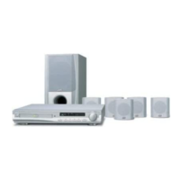
EasyManuals Logo
Home>JVC>Home Theater System>TH-A35

JVC TH-A35 Service Manual

JVC TH-A35
22 pages
To Next Page IconTo Next Page
To Previous Page IconTo Previous Page
Page #5 background imageLoading...
Page #5 background image
TH-A35
1-5
2. PIN CONFIGURATION
Disassembly method
Removing the cabinet top
Removing the tray Door
Removing the cabinet front
Removing the TUNER and panel rear
< CHAS, MAIN ASSEMBLY >
Removing the MPEG BOARD
Removing the MAIN BOARD
Removing FAN
Removing the Thermal - Regifer
Removing the VCD mechanism base assembly
Removing PWB, AMP
Removing Power , fruformer
< Front panel ASSEMBLY >
Removing the FRONT PWB & LED PWB
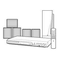
Commence disassembly of this set by removing the main units and then proceed to the components and
assemblies inside the units.
< MAIN BODY >

Other manuals for JVC TH-A35

Questions and Answers:

Question and Answer IconNeed help?

Do you have a question about the JVC TH-A35 and is the answer not in the manual?

JVC TH-A35 Specifications

Amplifier Section IconAmplifier Section
power per channel45 watts
impedance6 ohms
frequency1 kHz
Subwoofer IconSubwoofer
woofer size16 cm
sustained power capacity100 W
impedance10 Ω
Audio Section IconAudio Section
weight4.8 kg
frequency range25 Hz to 200 Hz
dimensions202 mm × 330 mm × 341 mm
Video Section IconVideo Section
dimensions92 mm × 97.5 mm × 92 mm
weight650 g
frequency range90 Hz to 20 kHz
Tuner Section IconTuner Section
FM tuning range87.50 MHz – 108.00 MHz
AM tuning range522 kHz – 1 629 kHz
power supply230 V, 50 Hz

Related product manuals