EasyManuals Logo
Home>JVC>Home Theater System>TH-A35

JVC TH-A35 Service Manual

JVC TH-A35
22 pages
To Next Page IconTo Next Page
To Previous Page IconTo Previous Page
Page #9 background imageLoading...
Page #9 background image
TH-A35
1-9
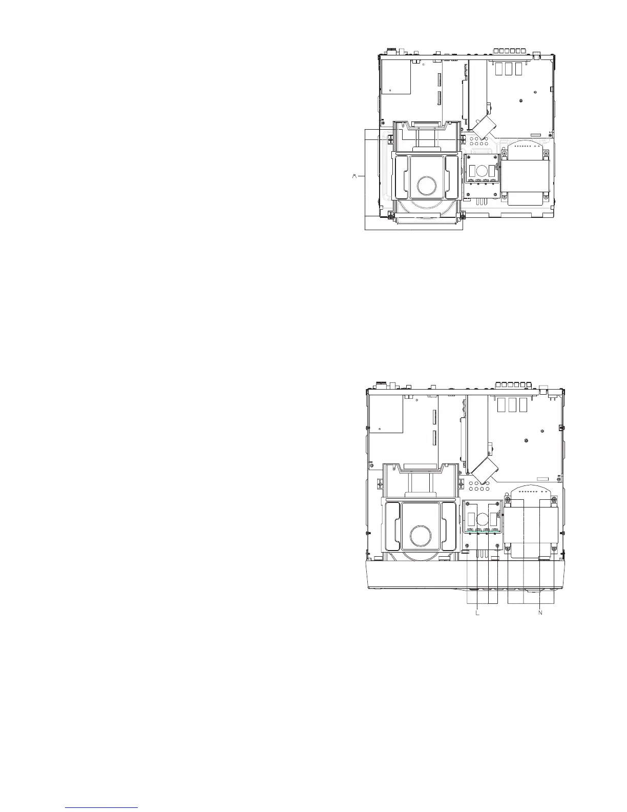
Removing the CD mechanism base
assembly
(See Fig.10)
Prior to performing the following procedure, remove
the cabinet front assembly.
1. Disconnect the harnesses from connector CN191
and CN192 on the main board and release them
from the cord stopper respectively.
2. Remove the four screws M attaching the
transformer assembly.
Removing PWB,AMP
(See Fig.11)
1. Unscrew 4 screws L.
2. Pull out connecter from PWB, AMP.
Removing Power, frusformer
(See Fig.11)
1. Unscrew 4 screws N
2. Untie wire connecter to PWB, MAIN.
Fig. 11
Fig. 10

Other manuals for JVC TH-A35

Questions and Answers:

Question and Answer IconNeed help?

Do you have a question about the JVC TH-A35 and is the answer not in the manual?

JVC TH-A35 Specifications

Amplifier Section IconAmplifier Section
power per channel45 watts
impedance6 ohms
frequency1 kHz
Subwoofer IconSubwoofer
woofer size16 cm
sustained power capacity100 W
impedance10 Ω
Audio Section IconAudio Section
weight4.8 kg
frequency range25 Hz to 200 Hz
dimensions202 mm × 330 mm × 341 mm
Video Section IconVideo Section
dimensions92 mm × 97.5 mm × 92 mm
weight650 g
frequency range90 Hz to 20 kHz
Tuner Section IconTuner Section
FM tuning range87.50 MHz – 108.00 MHz
AM tuning range522 kHz – 1 629 kHz
power supply230 V, 50 Hz

Related product manuals