Connections I Do not connect the power cord until all other connections have been made. I
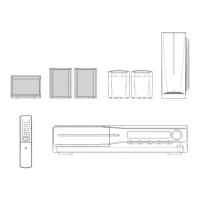
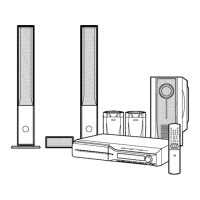
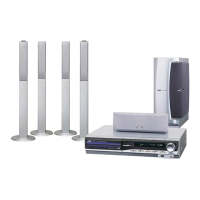
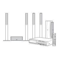
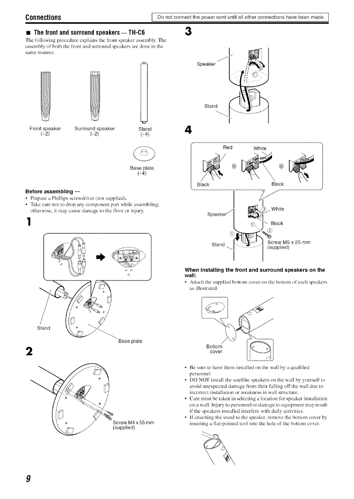
• The front and surround speakers i TH-C6 3
The following procedure explains the front speaker assembly. The
assembly of both the front and surround speakers are done in the
salne manner.
Speaker
Stand
Front speaker Surround speaker Stand 4
(x21 (x2) (×4)
Base plate
(x4)
Before assembling --
• Prcpare a Phillips scrcw&iver (not supplied).
• "l_&ecare not to drop any component part while assembling;
othcrwise, it may cause damage to the floor or injury.
1
o o
o
Stand
Base plate
2
\ + J Screw.M4 x 55 mm
' _ (supplied)
Red White
Black Black
Speaker j
Q
Stand .._f J,
_}....White
Black
Screw M5 x 25 mm
(supplied)
When installing the front and surround speakers on the
wall;
• Attach ll_esupplied bottom cover on the bottom of each speakers
as illustrated.
Bottom
cover
• Be sure to have them installed on the wall by a qualified
personnel.
• DO NOT install the satellite speakers on the wall by yourself to
avoid unexpected damage from their falling oft"the wall due to
incorrect installation or weakness in wall structure.
• Care must be taken in selecting a location for speaker installation
on a wall. Injury to personnel or damage to equipment may resuh
if the speakers installed interfere with daily activities.
• If attaching lhe stand to the speaker, remove the bottom cover by
inserting a fiat-pointed tool into the hole of the bottom covcn
9
 Loading...