1-22
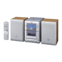
UX-A52R
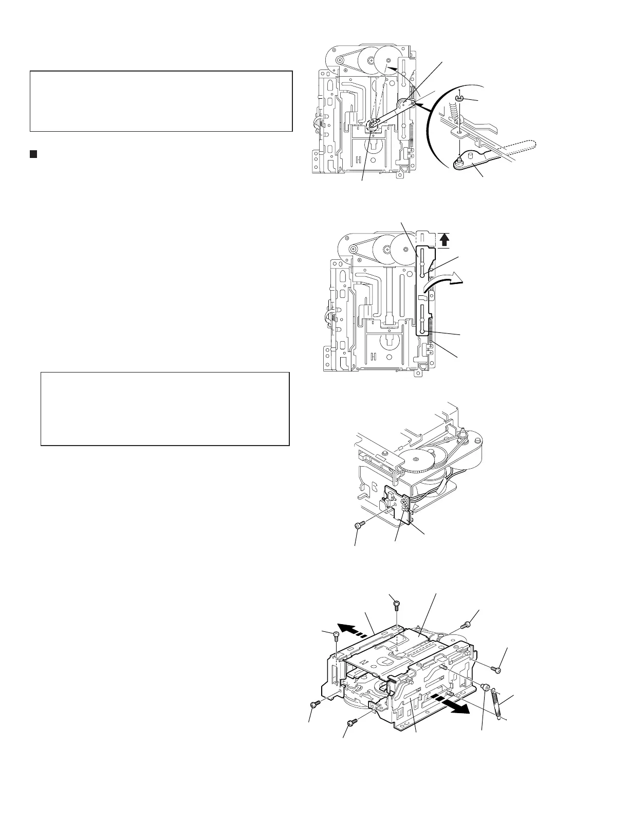
Remove the E-washer attaching the load arm on the
right side of the body.
Turn the load arm in the direction of the arrow to
release from the cassette hook at the joint a.
Remove the spring (1) attaching the trig lever.
Move the trig lever in the direction of the arrow and
release it from the two holes b.
Remove the screw A attaching the load board on
the right side of the body and unsolder the wire
extending from the sub motor.
1.
2.
3.
4.
5.
Remove the spring (2) and the holder collar on the
right side of the body.
Remove the two screws B attaching the side
bracket unit (R) in the direction of the arrow.
Remove the four screws C attaching the side
bracket (L) in the direction of the arrow.
6.
7.
8.
Removing the side bracket (L) and (R) /
load board (See Fig.1 to 4)
Prior to performing the following
procedures, turn the mode gear in the
direction of the arrow to move each section
to the eject position.
CAUTION:
The side bracket unit (R) can be
removed even if the load board is
attached. In such case, make sure to
unsolder the wire extending from the
sub motor.
REFERENCE:
<Cassette mechanism section>
Fig.1
Fig.2
Fig.3
Fig.4
Load arm
Load arm
E-washer
Joint a
Slide bracket
Hole b
Hole b
Spring (1)
A
C
C
C
C
B
B
Load board
Side bracket unit (R)
Side bracket unit (L)
Holder collar
Spring (2)
Soldering
Cassette hanger assembly
 Loading...