1-35
UX-A52R
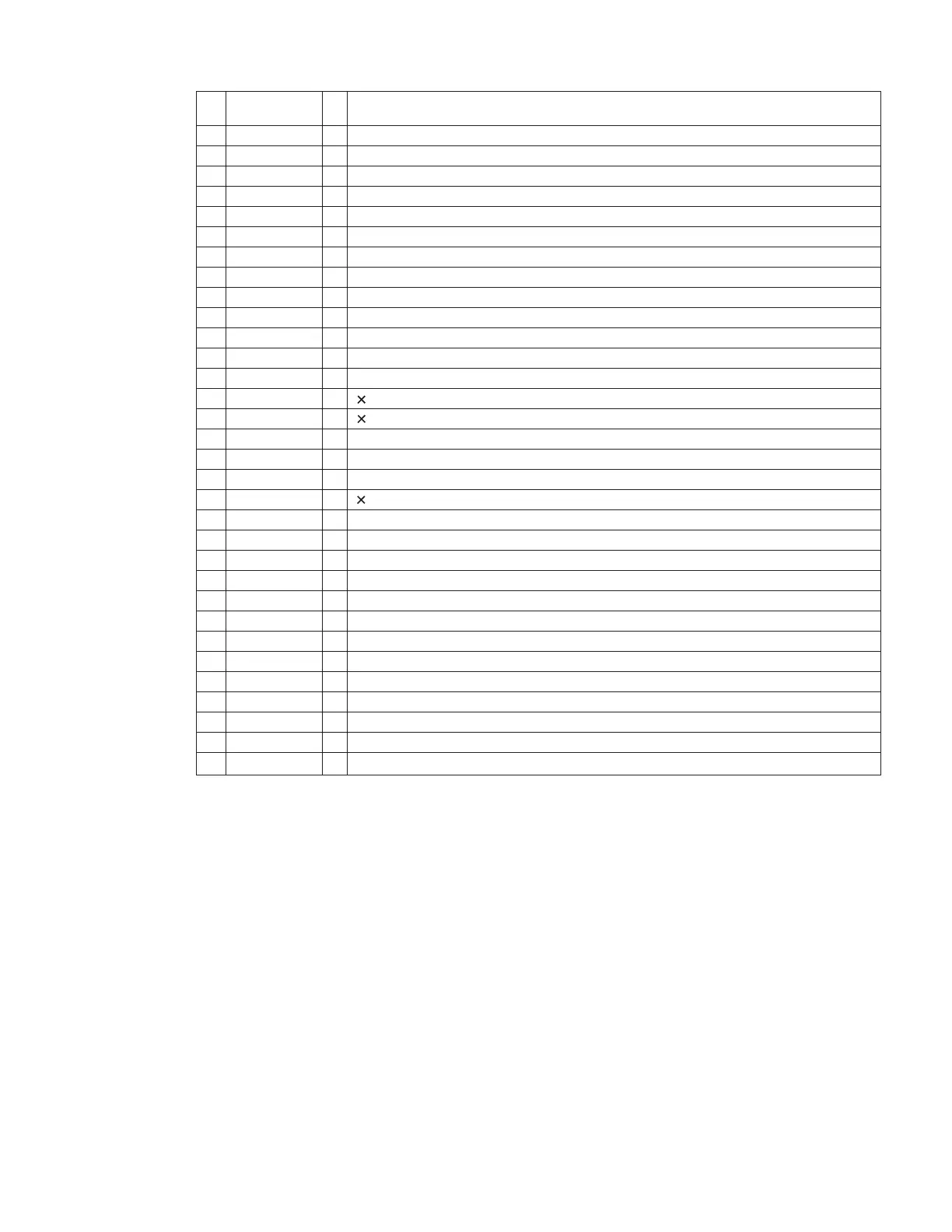
2. Pin function (2/2)
33
34
35
36
37
38
39
40
41
42
43
44
45
46
47
48
49
50
51
52
53
54
55
56
57
58
59
60
61
62
63
64
Pin
No.
Symbol I/O
Function
-
-
-
I
-
-
O
-
-
-
I
I
I
O
O
-
I
I
O
-
O
I
O
O
O
O
O
-
-
-
-
-
P10/AN10
AVREF
AVDD
/RESET
XT2
XT1
IC
X2
X1
VSS1
FLAG
BLKCK
/RFDET
EQx2
EQx4
VCOx4
OPEN
/CLOSE
IREFx4
P75/BUZ
/RESET
STAT
/DMUTE
/P.ON
MLD
MDATA
MCLK
CLKSW
JIG
JIG
JIG
JIG
Connected to GND
Analog circuit reference voltage. Connected with analog circuit power supply
Analog circuit power supply
CD control reset input from IC801
Not used
Connected with power supply
Flash memory control
Connected with external crystal oscillator
Connected with external crystal oscillator
GND
Flag signal input from IC651
Sub-code block clock signal input from IC651
RF signal amplitude detection input
2 equalizer switch output
4 equalizer switch output
Not used
Open door detection
Closed door detection
4 DSP current switch output
Not used
Reset signal output to IC651 (L: Reset)
Status signal input from IC651
Muting output to IC651
Power on/off switch signal output to IC291
Microcomputer command load signal output to IC651
Microcomputer command data output to IC651
Microcomputer command clock signal output to IC651
Not used
Not used
Not used
Not used
Connected to GND
 Loading...