(No.MB611)1-15
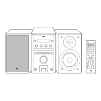
3.2.4 Removing the CD servo board
(See Fig.5 and 6)
• Remove the traverse mechanism assembly.
(1) Remove the two screws D attaching the CD servo board
from bottom side of traverse mechanism assembly. (See
Fig.5)
(2) Remove the solder from solder part e of the CD servo
board. (See Fig.5)
(3) Remove the yellow wire from solder part f of the CD servo
board. (See Fig.5)
(4) Remove the white wire from solder part h of the CD servo
board. (See Fig.5)
(5) Remove the CD servo board to upper side, disengage the
hook c to direction of the arrow 1 then turn over the CD ser-
vo board. (See Fig.5)
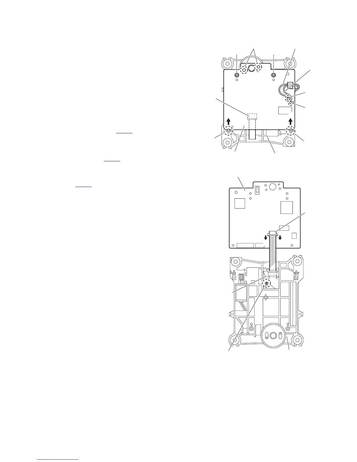
(6) Solder to short land part j of pickup. (See Fig.6)
(7) Release the lock of connector CN601
to direction of the ar-
row 2 and disengage the card wire. (See Fig.6)
Caution:
• Solder to short land part j of the pickup then disconnect the
card wire from connector CN601
of the CD servo board. If
disconnect the card wire before soldering, pickup is make
sure destroyed by static electricity. (See Fig.6)
• When reattaching the CD servo board, connect the card wire
to connector CN601
and then remove the solder of short
land part j of the pickup.
Fig.5
Fig.6
Traverse mechanism assemblyCD servo board
Yellow wire
White wire
Solder part e
Solder
part f
Solder
part g
DD
Hook h
CN601
Hook h
㧝㧝
Pickup
Short land part j
22
Traverse mechanism assembly
CD servo board
CN601
 Loading...