1-18 (No.MB611)
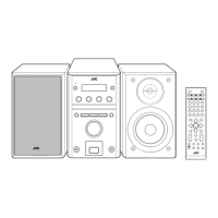
3.2.8 Removing the switch board
(See Fig.14)
(1) Disconnect the card wire from CN1
of the switch board
from bottom side of CD mechanism assembly.
(2) Remove the wire from solder part u of the switch board.
(3) Remove the one screw H attaching the switch board to CD
mechanism assembly.
(4) Lift up the switch board by pushing the hook v of CD mech-
anism assembly and take out it from part w.
Reference:
• After attach the switch board to CD mechanism assembly,
wire hooked to part x.
•Hook u of the CD mechanism assembly, it have to bond
lock.
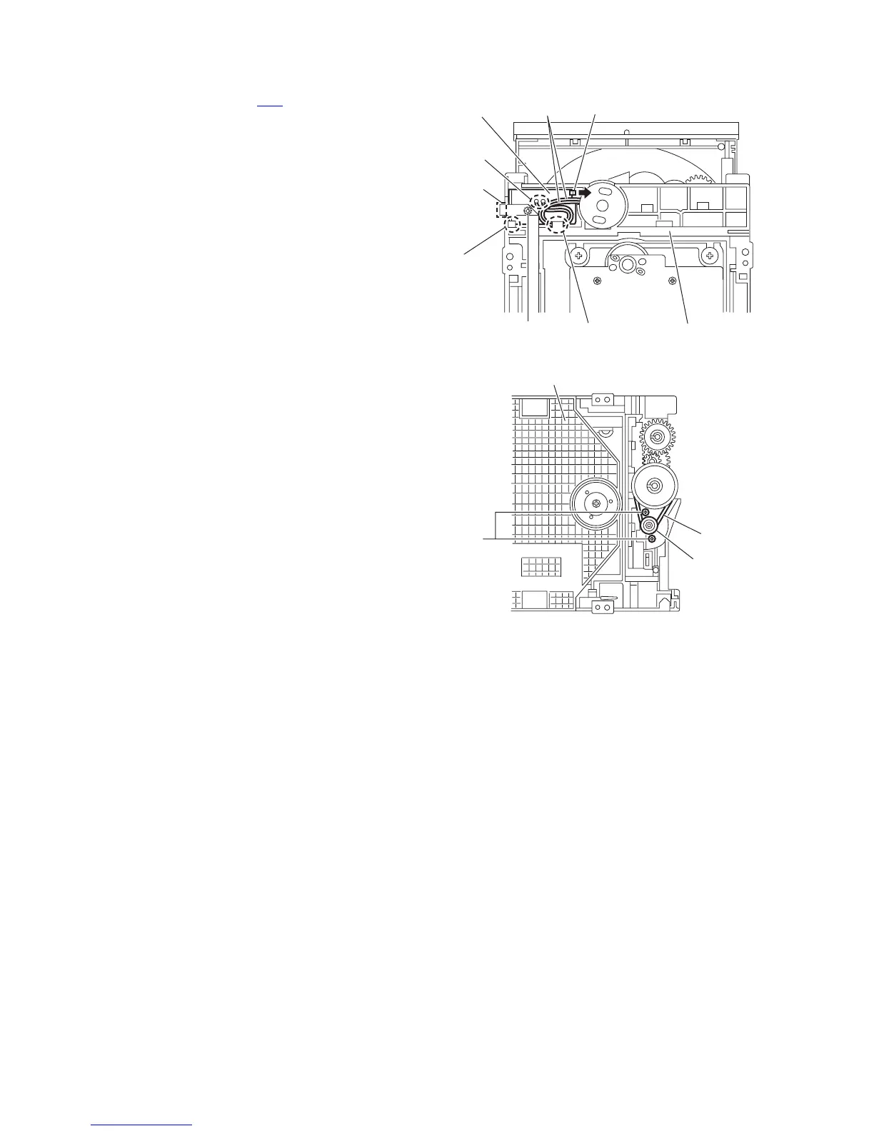
3.2.9 Removing the motor
(See Fig.14 and 15)
• Remove the tray assembly.
(1) Remove the wire from solder part u of the switch board
from bottom side of CD mechanism assembly.
(2) Remove the belt of motor pulley from upper side of CD
mechanism assembly. (See Fig.15)
Caution:
Belt should not apply grease.
(3) Remove the two screws J attaching the motor to CD mech-
anism assembly and take out the motor from bottom side
of CD mechanism assembly. (See Fig.15)
Reference:
After motor attached to CD mechanism assembly, wire should
hook to part w. (See Fog.14)
Fig.14
Fig.15
Switch board Wire
Solder
part u
Hook v
Part w
CN1
CD mechanism assembly
H
Part w
CD mechanism assembly
J
Belt
Motor pulley
 Loading...