(No.MB682<Rev.001>)1-17
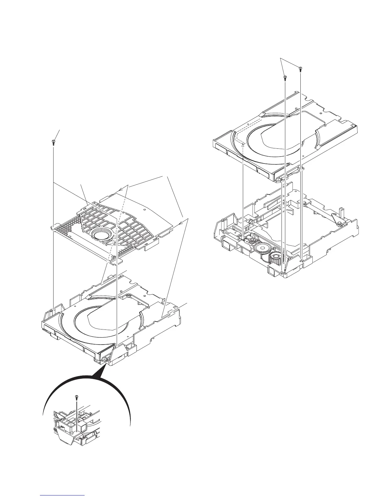
3.2.5 Removing the tray assembly
(See Fig.14 & 15)
(1) Remove the two screws J attaching the clamper base.
(See Fig.14)
(2) Remove the one screw K attaching the shaft guide from
bottom side. (See Fig.14)
(3) Remove the two screws L attaching the shaft guide from
top side. (See Fig.15)
Caution:
When attach the tray assembly, boss of loading sub assembly
should attach to guide of bottom side at tray assembly. (See
Fig.15)
Fig.14
Fig.15
J
order 1
order 2
clamper base
K
[bottom side]
L

 Loading...