(No.MB682<Rev.001>)1-9
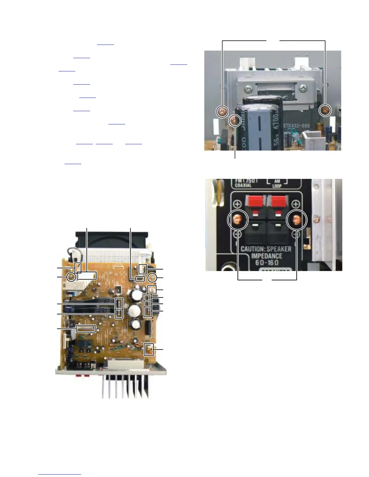
3.1.4 Removing the Amp board (See Fig.8 to 10)
(1) Disconnect the Connector wire from Front jack board con-
nected to connector CN201
of the Amp board. (See Fig.8)
(2) Disconnect the card wire from Micom board connected to
connector CN204
of the Amp board. (See Fig.8)
(3) Disconnect the flat wires connected to connectors CN207
and CN208 of the Amp board. (See Fig.8)
(4) Disconnect the card wire from Micom board connected to
connector CN205
of the Amp board. (See Fig.8)
(5) Disconnect the card wire from DVD mechanism connected
to connector CN213
of the Amp board. (See Fig.8)
(6) Disconnect the flat wire from Front jack board connected to
connector CN203 of the Amp board. (See Fig.8)
(7) Disconnect the connector wire from Power transformer
connected to connector CN209
of the Amp board. (See
Fig.8)
(8) Disconnect the flat wire s from Power board connected to
connectors CN210
, CN211 and CN212 of the Amp board.
(See Fig.8)
(9) Disconnect the connector wire from FAN connected to con-
nector CN206
of the Amp board. (See Fig.8)
(10) Remove the two screws G attaching the Amp board. (See
Fig.8)
(11) Remove the two screws H attaching the Heat sink bracket.
(See Fig.9)
(12) Remove the one screw J attaching the Amp board. (See
Fig.9)
(13) Remove the two screws K attaching the Speaker terminal.
(See Fig.10)
Fig.8
Fig.9
Fig.10
GG
CN201
CN207
CN208
CN205
CN204 CN203
CN213
CN209
CN212
CN211
CN210
CN206
J
H
K
 Loading...