
Do you have a question about the JVC UX-G950VB and is the answer not in the manual?
| Number of Channels | 2 |
|---|---|
| RMS Output Power | 50 W |
| Tuner | FM/AM |
| Bluetooth | Yes |
| USB Port | Yes |
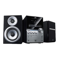
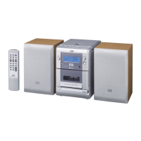
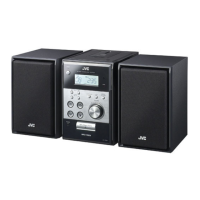
| Type | Micro System |
| Disc Compatibility | CD, CD-R/RW |
Detailed specifications for the UX-G950V amplifier, tuner, disc player, USB, and general features.
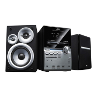
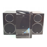
Detailed specifications for the UX-G650 amplifier, tuner, disc player, USB, and general features.
Covers safety precautions, warnings, cautions, and critical safety parts identification.
Guidance on preventing static discharge and safely handling the optical pickup unit.
Important safety information regarding laser radiation exposure and precautions.
Instructions for removing the metal cover of the main body, referencing figures.
Procedures for removing the front panel and tuner pack from the main unit.
Steps for removing the amplifier board and the rear panel.
Instructions for removing the Micom, Front Jack, Power, and FL boards.
Procedure for removing the function board, including the volume knob.
Detailed steps for removing the DVD traverse mechanism and pickup assembly.
Instructions for removing feed motor, spindle motor, and tray assemblies.
Important notes for servicing the DVD section, including EEPROM initialization.
Guide to entering and using the DVD/CD test mode for diagnostics and adjustments.
Instructions for accessing and utilizing the system micom test mode.
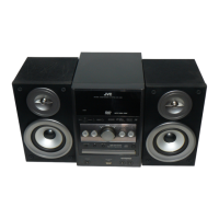
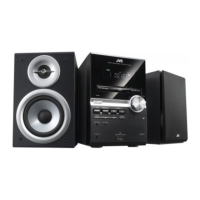
Exploded view and parts list for the general assembly of the micro component system.
Detailed parts list for the DVD mechanism assembly.
Detailed parts list for the DVD loading base assembly.
Comprehensive list of electrical components by board, including resistors and capacitors.
List of packing materials and accessories included with the product.
Overview of the system's functional blocks and their interconnections.
Detailed schematic diagrams for the primary and power supply sections.
Layout diagrams for primary, FL, jack, mic, micom, amp, and front end boards.