1-6
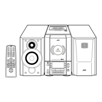
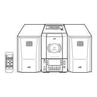
UX-V30
Prior to performing the following procedure, remove
the rear cover, the side panels, the cassette
mechanism assembly and the main board.
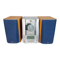
Disconnect the card wire from connector CN732 on
the LCD board.
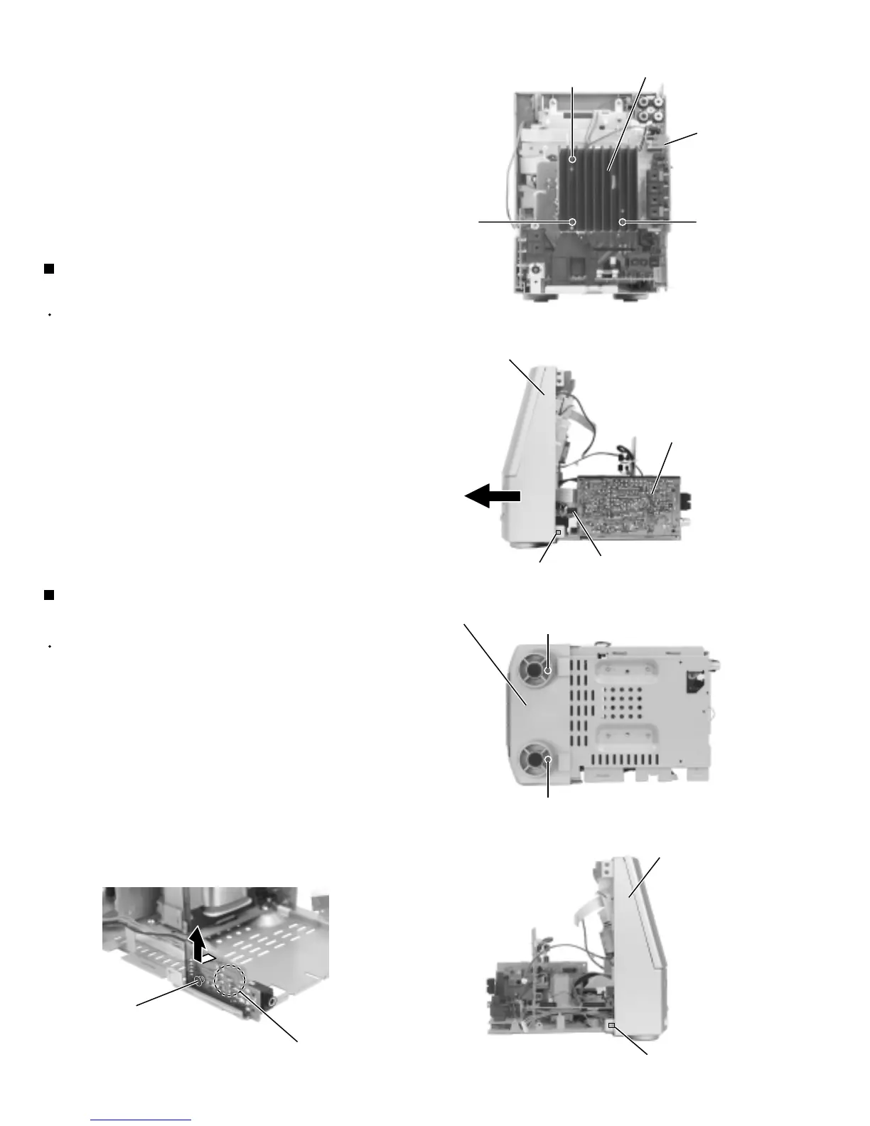
Remove the two screws D attaching the front panel
assembly on the bottom of the body.
Release the two joints c on the lower right and left
sides of the body. Pull out the front panel assembly
toward the front.
1.
2.
3.
Removing the front panel assembly
(See Fig.10 to 12)
Prior to performing the following procedure, remove
the rear cover, the side panels, the cassette
mechanism assembly, the main board and the front
panel assembly.
Remove the plastic rivet attaching the head phone
board and release the joint d.
1.
Removing the head phone board
(See Fig.13)
Fig.9
Fig.10
Fig.11
Fig.12Fig.13
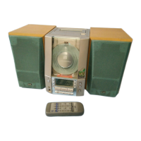
Main board
Heat sink
G
G
F
Front panel assembly
Joint c
LCD board
CN732
Front panel assembly
D
D
Joint c
Front panel assembly
Joint d
Plastic rivet
Tuner & function board
 Loading...