(No.MB618)1-7
SECTION 2
SPECIFIC SERVICE INSTRUCTIONS
This service manual does not describe SPECIFIC SERVICE INSTRUCTIONS.
SECTION 3
DISASSEMBLY
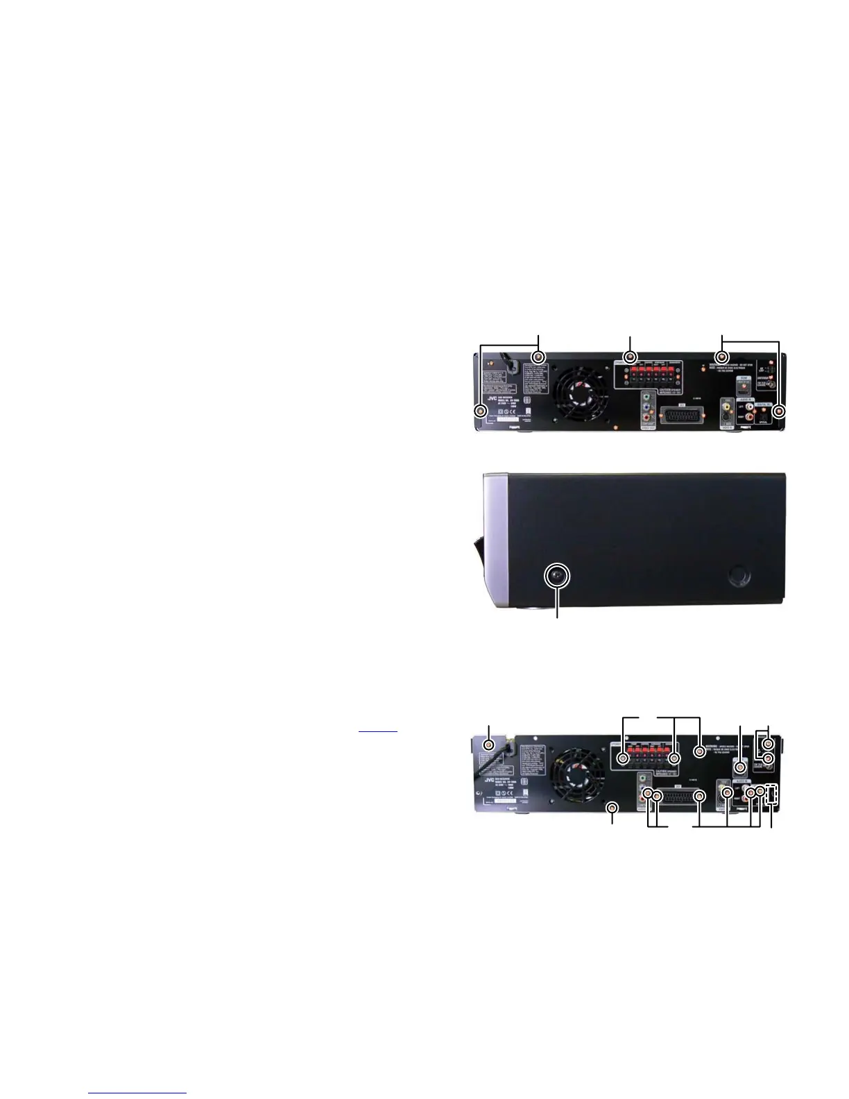
3.1 Main body
3.1.1 Removing the METAL COVER (See Fig.1, 2)
(1) Remove the four screws A attaching the METAL COVER.
(See Fig.1)
(2) Remove the one screw B attaching the METAL COVER by
use TORX driver. (See Fig.1)
TROX driver: size T 10
Parts number: DR-L70
(3) Remove the two screws C attaching the both side of MET-
AL COVER. (See Fig.2)
Fig.1
Fig.2
3.1.2 Removing the REAR PANEL (See Fig.3)
(1) Remove the power cord from POWER BOARD assembly.
(2) Remove the two screws D attaching the TUNER PACK and
then disconnect the card wire from connector CN205
of the
MAIN BOARD assembly.
(3) Remove the three screws E attaching the AMP BOARD as-
sembly.
(4) Remove the one screw F attaching the POWER BOARD
assembly.
(5) Remove the one screw G attaching the HDMI BOARD as-
sembly.
(6) Remove the six screws H attaching the each I/O jack.
(7) Remove the one screw J attaching the REAR PANEL.
Fig.3
AAB
C
EGFD
CN205
J
H
 Loading...