1-8 (No.MB618)
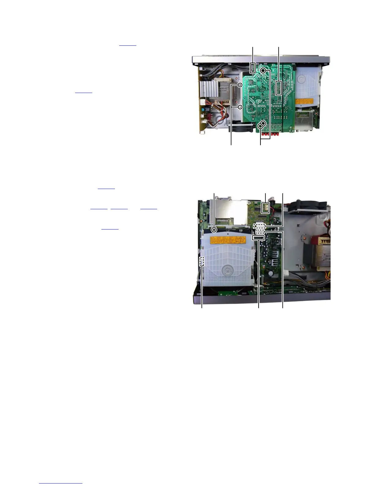
3.1.3 Removing the AMP BOARD assembly (See Fig.4)
(1) Disconnect the connector wire from POWER BOARD as-
sembly connected to connector CN501
of the AMP
BOARD assembly.
(2) Remove the two screws K attaching the HEAT SINK
BRACKET.
(3) Remove the three screws L attaching the AMP BOARD as-
sembly.
(4) Disconnect the CONNECTION BOARD assembly con-
nected connector CN504
of the AMP BOARD assembly.
Fig.4
3.1.4 Removing the DVD MECHANISM assembly (See Fig.5)
(1) Disconnect the connector wire from MAIN BOARD assem-
bly connected to connector CN811
of the DVD BOARD as-
sembly.
(2) Disconnect the card wires from DVD BOARD assembly
connected to connector CN201
, CN202 and CN204 of the
MAIN BOARD assembly.
(3) Disconnect the card wire from DVD MECHANISM assem-
bly connected to connector CN212
of the MAIN BOARD
assembly.
(4) Remove the one screw M attaching the DVD MECHANISM
assembly.
Fig.5
KL
CN504CN501
CN201
CN811
CN212
M
CN204
CN202
 Loading...