14
Description
Differential voltage input
0...±10 VDC ^ 0...±maximum speed; Ri = 55 kÙ
Programmable analog output 0...±10 VDC / 5 mA;
Function is defined by the machine builder
Reference voltage output for set value potentiometer
(+10 VDC / max. 4 mA)
Ground for analog in- and output
The function of the programmable inputs is defined by
the machine builder.
Switching voltage 13...30 VDC ± 0 % smoothed
Ri=2,1 kÙ
Supply of the driver stage
This input must be supplied with an external voltage of
20...30 VDC ± 0 % / 0,2 A (U
BR
max. 3,6 Vss). When
switching off this voltage an error reset is executed.
Programmable digital output 1 and 2
Load capacity maximal 50 mA for both outputs
Function is defined by the machine builder
Supply of the control
This input must be supplied with an external voltage of
20...30 VDC ± 0 % / 0,8 A (U
BR
max. 3,6 Vss). Through
the separate supply the control can also be operated at
switched off driver/power section.
Reference potential for digital inputs/outputs
Programmable relay output
Load capacity max. 30 VDC / 0,01...1 A
Function is defined by the machine builder
Installation and Connection
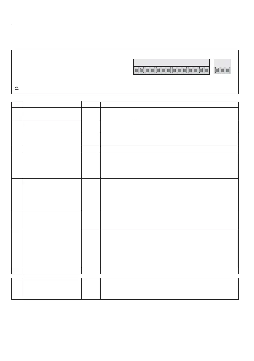
3.5 Control board
3.5.1 Control terminal strip X2A
1257810111213 24 25 2616 18 19 21 22
• Tightening torque 0,22...0,25 Nm (2 lb inches)
• Use shielded/drilled cables
• Lay shield on one side of the inverter onto earth
potential
X2A
NPN control is not possible at the A servo !
PIN
1
2
5
7
8
10
11
12
13
16
18
19
21
22
24
25
26
Function
+ Set value input 1
- Set value input 1
Analog output
+10V output
Analog ground
Progr. input 1
Progr. input 2
Progr. input 3
Progr. input 4
Voltage supply
driver stage
Transistor output 1
Transistor output 2
Voltage supply
Control board
Digital ground
Relay 1 / NO contact
Relay1 / NC contact
Relay1 / switching contact
Name
AN1+
AN1-
AN
OUT1
CRF
COM
I1
I2
I3
I4
ST
O1
O2
Uin
0V
FLA
FLB
FLC
 Loading...


