6
2.3 Technical data
Product description
Site altitude max. 2000 m. With site altitudes over 1000 m a derating of 1% per 100 m must
be taken into consideration.
1)
Max. current before the responding of the OL function. With the regulated systems 5% are to
be subtracted as control reserve.
2)
Amount of heat to be dissipated over the mounting surface at rated operation.
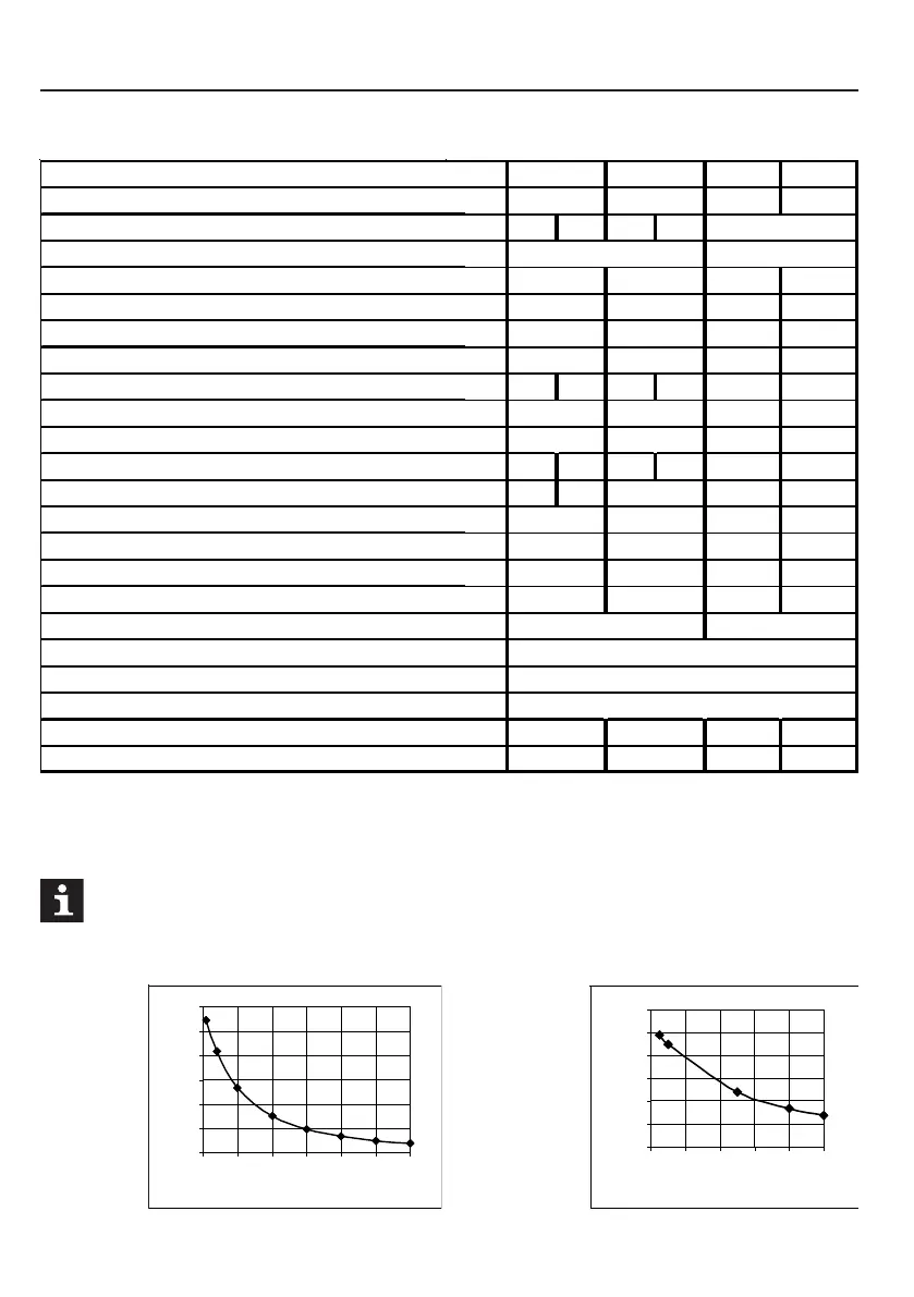
Overload function
07...09.F5
04.F5
04 07 04 09
AAAA
1313 3
[V]
230 400
[kVA] 0,8 1,6 1,0 2,8
[A] 2 4 1,4 4,1
[A] 8 8 5,6 8,2
[A] 9,6 9,6 6,7 9,8
[A] 4 2,6 8 5,6 1,8 6
[kHz] 8 8 8 4
[kHz] 8 8 8 8
[W]43355550 45 65
[W] 25 20 - 28 -
Ohm] 82 60 150 110
Ohm] 82 82 330 160
[A] 5,5 7 5,5 7,5
[A] 2,3 4 1,6 4,1
[V] 180...260 ±0 305...500 ±0
[Hz] 50 / 60 +/- 2
[V] 3 x 0...U
[Hz] 0...400
[m] 10 - 10 -
[m] 40 50 20 50
0 s
20 s
40 s
60 s
80 s
100 s
120 s
100
%
150
%
200
%
250
%
300
%
350
%
400
%
0 s
50 s
100 s
150 s
200 s
250 s
300 s
100
%
120
%
140
%
160
%
180
%
200
%
Servo size
Housing size
Phases
Input rated voltage
Output rated power
Output rated current
Max. short time current
OC-tripping current
Input rated current
Rated switching frequency
Max. switching frequency
Power loss at rated operation
Power modules losses
Min. braking resistor
Typ. braking resistor
Max. braking current
Stand still current at rated operation
Mains voltage U
Mains frequency
Output voltage
Output frequency
Max. motor line length (shielded)
Max. motor line length (unshielded)
 Loading...


