10
3.3 Connection of Power Circuit
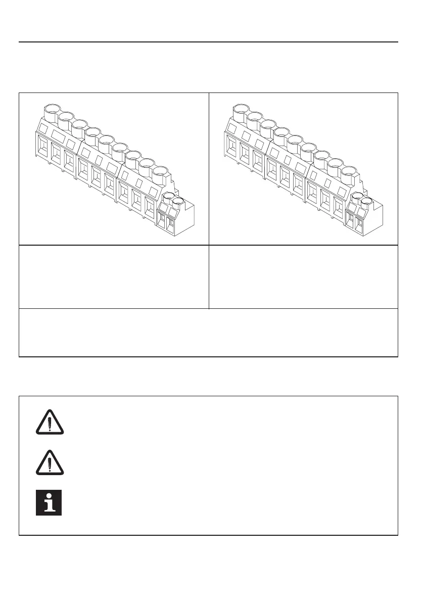
3.3.1 Terminal Strip X1A
3.3.2 Wiring instructions
W
V
U
PB
--
++
L3
N/L2
L1
T1
T2
W
V
U
PB
--
++
L3
L2
L1
T1
T2
Installation and Connection
Terminal strip X1A/ 230 V class suitable for
• 180...260 V AC / 1-phase (L1/N)
• 180...260 V AC / 3-phase (L1, L2, L3)
• DC-Supply 250...370 V DC (++, --)
Terminal strip X1A/ 400 V class suitable for
• 305...500 V AC / 3-phase (L1, L2, L3)
• DC-Supply 420...720 V DC (++, --)
Absolutely observe the connecting voltage of the KEB COMBIVERT.
A 230V-unit will be immediately destructed on a 400V-power supply.
Never exchange the mains and motor cables.
Some countries demand that the PE-terminal is directly connected
to the terminal box (not over the mounting plate).
• ++, PB Braking resistor
• U, V, W Motor
• T1, T2 Temperature sensor / switch (see chapter 3.3.6)
 Loading...


