11
++
--
W
T1
L1
PE
N
X1A
U
PB
V
W
L1
N/L2
L3
T2
PE
U
T1
T2
W
V
L1
PE
X1A
L2
L3
++
--
L3
L1
PE
N/L2
PB
U
PB
T1
T2
W
V
L1
PE
X1A
L2
L3
++
--
L3
L2
L1
PE
U
PB
T1
T2
N/L2
V
X1A
-
+
++
--
L3
W
L1
PE
U
PB
T1
T2
L2
V
X1A
-
+
++
--
L3
W
L1
PE
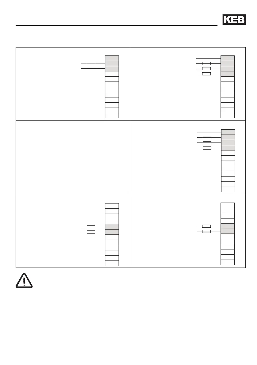
Mains connection 230 V 1-phase Mains connection 230 V 3-phase
Mains connection 400 V 3-phase
DC-connection 230 V-class
DC-connection 400 V-class
1 x 180...260 V AC
3 x 180...260 V AC
3 x 305...500 V AC
250...370 V DC
420...720 V DC
3.3.3 Mains connection
Installation and Connection
Protection
• Fuse (see chapter 2.3) or
• power protective switch
• 1-phase inverter RCD type A or type B
• 3-phase inverter RCMA with separator or
RCD type B
• at DC-supply pay attention to the
permissible voltage range of the fuses
Separate supply of the control
Without further cooling measure a separate supply of the control is not permissible
during a longer period, because the interior fan is not controlled here. The occuring heat
accumulation causes an accelerated aging of the components and thus for a reduction
of the economic life time.
 Loading...


