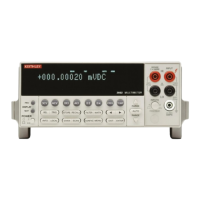
DC VOLTS
DCV INPUT CHARACTERISTICS AND ACCURACY
ENHANCED ACCURACY
1
- 10PLC, DFILT 10
RELATIVE ACCURACY TEMP.
FULL RESO- INPUT ±(ppm of reading + ppm of range) COEFFI-
RANGE SCALE LUTION RESISTANCE Transfer
5
24 Hours
2
90 Days
3
1 Year
3
2 Years
3
CIENT*
200 mV
4
±210.000000 1 nV >100 G
Ω
0.4 + 1.5 3.5 + 3 15 + 8 19 + 9 23 + 10 2 + 1.8
2V
4
±2.10000000 10 nV >100 G
Ω
0.2 + 0.15 1.2 + 0.3 6 + 0.8 10 + 0.9 14 + 1 0.2 + 0.18
20 V ±21.0000000 100 nV >100 G
Ω
0.1 + 0.05 1.2 + 0.1 6 + 0.15 10 + 0.15 14 + 0.15 0.3 + 0.02
200 V ±210.000000 1 µV 10 M
Ω
±1% 0.5 + 0.08 5 + 0.4 14 + 2 22 + 2 30 + 2 1.5 + 0.3
1000 V
6
±1100.00000 10 µV 10 M
Ω
±1% 1 + 0.05 5 + 0.08 14 + 0.4 22 + 0.4 30 + 0.4 1.5 + 0.06
* ± (ppm of reading + ppm of range)/°C Outside T
CAL
± 5°C
1. Specifications are for 10 power line cycles, synchronous autozero, 10-reading repeat digital filter, autorange off, except as noted.
2. For TCAL ±1°C, following 4-hour warm-up. TCAL is ambient temperature at calibration (23°C at the factory). Add 0.5 ppm of reading
uncertainty if the unit is power cycled during this interval.
3. For TCAL ±5°C, following 4-hour warm-up.
4. Care must be taken to minimize thermal offsets due to operator cables.
5. Specifications apply for 20-reading repeat digital filter, TREF ± 0.5°C (TREF is the initial ambient temperature), and for measurements with-
in 10% of the initial measurement value and within 10 minutes of the initial measurement time.
6. Add 2.5ppm
×
(V
IN
/1000V)
2
additional uncertainty for inputs above 200V, except in transfer accuracy specifications.
DC VOLTAGE UNCERTAINTY
= ± [ (ppm of reading)
×
(measured value) + (ppm of range)
×
(range used) ] / 1,000,000.
% ACCURACY
= (ppm accuracy) /10,000.
1PPM OF RANGE
= 20 counts for ranges up to 200V and 10 counts on 1000V range at 7
½
digits.
KEITHLEY FACTORY CALIBRATION UNCERTAINTY
RANGE ppm of reading
200 mV 3.2
2 V 3.2
20 V 2.6
200 V 2.6
1000 V 2.6
AC VOLTS
NORMAL MODE RMS
1
90 Days, 1 Year or 2 Years, ±2°C from last AC self-cal for 1% to 100% of range
2
, ±(% of reading + % of range)
100– 0.2–
RANGE 20–50Hz 50–100Hz 0.1–2kHz 2–10kHz 10–30kHz 30–50kHz 50–100kHz 200kHz 1MHz 1–2MHz
200 mV 0.25+0.015 0.07+0.015 0.02 + 0.01 0.02 + 0.01 0.025 + 0.01 0.05 + 0.01 0.17+0.015 0.5+0.025 2+0.1 5+0.2
2 V 0.25+0.015 0.07+0.015 0.02 + 0.01 0.02 + 0.01 0.025 + 0.01 0.05 + 0.01 0.17+0.015 0.5+0.025 2+0.1 5+0.2
20 V 0.25+0.015 0.07+0.015 0.03+0.015 0.04+0.015 0.05 +0.015 0.07+0.015 0.17+0.015 0.5+0.025 4+0.2 7+0.2
4
200 V
3
0.25+0.015 0.07+0.015 0.03+0.015 0.04+0.015 0.05 +0.015 0.07+0.015 0.17+0.015 0.5+0.025
4
4+0.2
4
750 V
3
0.25+0.015 0.1 +0.015 0.05+0.015 0.06+0.015 0.08 +0.015 0.1+0.015
4
0.5 +0.015
4
1. Specifications apply for sinewave input, AC + DC coupling, 1 power line cycle, autozero on, digital filter off, following 55-minute warm-up.
2. For 1% to 5% of range below 750V range, and for 1% to 7% of 750V range, add 0.01% of range uncertainty. For inputs from 200kHz to
2MHz, specifications apply above 10% of range.
3. Add 0.001% of reading
×
(V
IN
/100V)
2
additional uncertainty above 100V rms.
4. Typical values.
Specs and Accessories 4-3
Factory calibration uncertainty represents traceability to NIST. This uncertainty is added
to relative accuracy specifications to obtain absolute accuracies. The 200mV and 2V range
uncertainties are equal to the uncertainty of the 2V calibration source. The 20V, 200V, and
1000V range uncertainties are equal to the uncertainty of the 20V calibration source.

 Loading...