DC CURRENT UNCERTAINTY
= ± [ (ppm reading)
×
(measured value) + (ppm of range)
×
(range used) ] / 1,000,000.
% ACCURACY
= (ppm accuracy) / 10,000.
5PPM OF RANGE
= 10 counts at 6
½
digits.
DC IN-CIRCUIT CURRENT
The DC in-circuit current measurement function allows a user to measure the current through a wire or a circuit board trace without breaking the
circuit.
When the In-Circuit Current Measurement function is selected, the 2002 will first perform a 4-wire resistance measurement, then a voltage mea-
surement, and will display the calculated current.
TYPICAL RANGES:
Current:
100µA to 12A.
Trace Resistance:
1m
Ω
to 10
Ω
.
Voltage:
±200mV max. across trace.
Speed:
4 measurements/second at 1 power line cycle.
Accuracy:
±(5% +500µA). For 1 power line cycle, autozero on, 10-
reading digital filter, T
CAL
±5°C, 90 days, 1 year or 2 years.
AC AMPS
ACI ACCURACY
1,2
90 Days, 1 Year or 2 Years, T
CAL
±5°C, for 5% to 100% of range, ±(% of reading + % of range)
RANGE 20Hz–50Hz 50Hz–200Hz 200Hz–1kHz 1kHz–10kHz 10kHz–30kHz
3
30kHz–50kHz
3
50kHz–100kHz
3
200 µA 0.35 + 0.015 0.2 + 0.015 0.4 + 0.015 0.5 + 0.015
2 mA 0.3 + 0.015 0.15 + 0.015 0.12 + 0.015 0.12 + 0.015 0.25 + 0.015 0.3 + 0.015 0.5 + 0.015
20 mA 0.3 + 0.015 0.15 + 0.015 0.12 + 0.015 0.12 + 0.015 0.25 + 0.015 0.3 + 0.015 0.5 + 0.015
200 mA 0.3 + 0.015 0.15 + 0.015 0.12 + 0.015 0.15 + 0.015 0.5 + 0.015 1 + 0.015 3 + 0.015
2 A 0.35 + 0.015 0.2 + 0.015 0.3 + 0.015 0.45 + 0.015 1.5 + 0.015 4 + 0.015
1. Specifications apply for sinewave input, AC+DC coupling, 1 power line cycle, autozero on, digital filter off, following 55-minute warm-up.
2. Add 0.005% of range uncertainty for current above 0.5A rms for self-heating.
3. Typical values.
AC CURRENT UNCERTAINTY
= ±[ (% of reading) × (measured value) + (% of range) × (range used) ] / 100.
PPM ACCURACY = (% accuracy) × 10,000.
0.015% OF RANGE = 30 counts at 5½ digits.
FREQUENCY COUNTER
FREQUENCY/PERIOD INPUT CHARACTERISTICS AND ACCURACY 90 Days, 1 Year or 2 Years
MINIMUM SIGNAL LEVEL
2
ACCURACY
FREQUENCY PERIOD RESO- 1HZ– MAXIMUM TRIGGER ±(% of
RANGE
1
RANGE LUTION 1MHz 1–5MHz 5–15MHz INPUT LEVEL reading)
AC Voltage Input 1Hz–15 MHz 67 ns – 1 s 5 digits 60mV 60 mV 350 mV 1100 V pk
1
0–600V 0.03
AC Current Input 1Hz– 1 MHz 1 µs – 1 s 5 digits 150 µA 1 A pk 0–600mA 0.03
1. Subject to 2 × 10
7
V•Hz product (for inputs above 20V).
2. Valid for the lowest range. For each range increase, multiply these numbers by 10.
TIME BASE: 7.68MHz ± 0.01%, 0°C to 55°C.
READING TIME: 420ms maximum.
VOLTAGE INPUT IMPEDANCE: 1MΩ ±2% with <140pF.
TRIGGER LEVEL ADJUSTMENT: Trigger level is adjustable in 0.5% of range steps to ±60% of range in real-time using the up and down
range buttons.
FREQUENCY RANGING: Autoranging from Hz to MHz.
FREQUENCY COUPLING: AC + DC or AC only.
Specs and Accessories 4-5
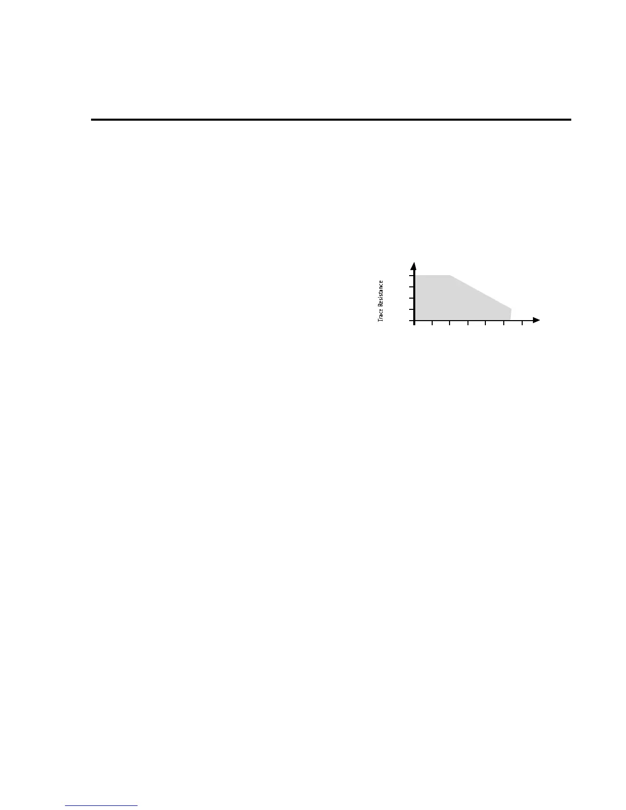
MEASUREMENT RANGE CHART
10Ω
1Ω
100mΩ
10 m Ω
1mΩ
1mA 10mA100mA 1A 10 A 100A10 0 µA
Measured Current
Specified
Measurement
Range

 Loading...


