Calibration
2-17
INPUT = 20.0000000 V
(At this point, you can use the cursor and range keys to set
the calibration voltage to a value from 9.5 to 20.5V if your
calibrator cannot source 20V.)
9. Press ENTER. The instrument will display the
following message to indicate it is performing 20V DC
calibration:
Performing 20 VDC Calibration
Step 5: Ohms calibration
1. After completing 20VDC calibration, the instrument
will display the following:
CONNECT 1 MΩ 4W
2. Set the calibrator output to 1.00000MΩ, and make sure
that external sense is turned on.
NOTE
Be sure that the calibrator external sense
mode is turned on when calibrating all re-
sistance ranges.
3. Press ENTER, and note that the Model 2002 displays
the resistance calibration value:
INPUT = 1.0000000 MΩ
4. Using the cursor and range keys, set the resistance value
displayed by the Model 2002 to the exact resistance val-
ue displayed by the calibrator. (The allowable range is
from 475kΩ to 1.025MΩ.)
5. Press ENTER, and note that the instrument displays the
following during 1MΩ calibration:
Performing 1 MΩ Calibration
6. After completing 1MΩ calibration, the instrument will
display the following:
CONNECT 100 kΩ 4W
7. Set the calibrator output to 100kΩ, and make sure that
external sense is turned on.
8. Press ENTER, and note that the Model 2002 displays
the resistance calibration value:
INPUT = 100.00000 kΩ
9. Using the cursor and range keys, set the resistance value
displayed by the Model 2002 to the exact resistance val-
ue displayed by the calibrator. (The allowable range for
this parameter is from 95kΩ to 205kΩ.)
10. Press ENTER to complete the 200kΩ calibration step.
11. Repeat steps 7 through 10 for the 20kΩ, 2kΩ, 200Ω, and
20Ω ranges in that order. Be sure the set the calibrator
and Model 2002 to the correct resistance value as
follows:
Step 6: DC amps calibration
1. After ohms calibration is completed, the instrument will
prompt you for the first DC amps calibration step:
CONNECT 200 µADC
2. Connect the DC amps calibrator to the AMPS and
INPUT LO terminals (see Figure 2-3).
3. Set the calibrator output to 200.000µA, and make sure
the unit is in operate. (The allowable range is from 95µA
to 205µA.)
4. Be sure that the displayed current matches the calibra-
tion value, then press ENTER to complete this calibra-
tion step.
5. Repeat steps 3 and 4 for the remaining amps calibration
points as follows:
Step 7: Open-circuit calibration
1. At this point, the instrument will display the following
message advising you to disconnect test leads:
OPEN CIRCUIT INPUTS
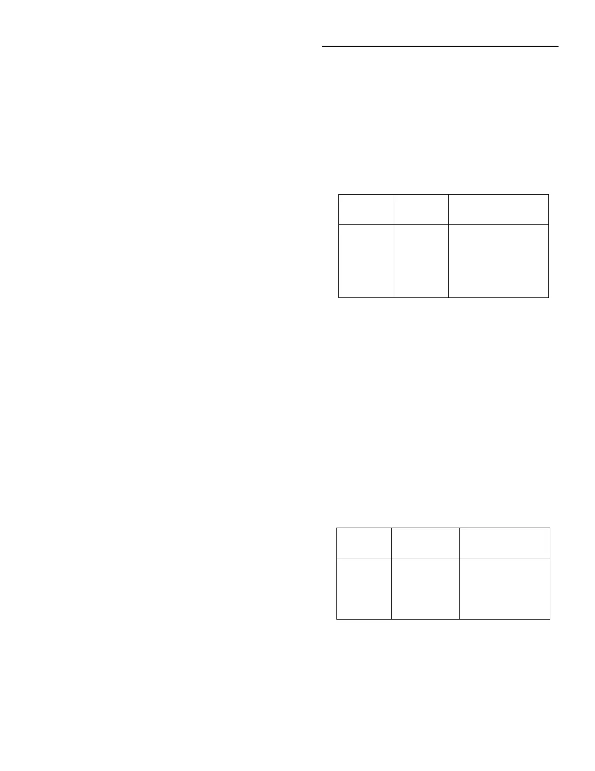
Calibration
step
Calibration
value* Allowable range
2MΩ
200kΩ
20kΩ
2kΩ
200Ω
20Ω
1MΩ
100kΩ
19kΩ
1.9kΩ
190Ω
19Ω
475kΩ to 1.025MΩ
95kΩ to 205kΩ
9.5kΩ to 20.5kΩ
0.95kΩ to 2.05kΩ
95Ω to 205Ω
9.5Ω to 20.5Ω
* Nominal values shown. Use exact calibrator value.
Calibration
step
Calibrator
current Allowed range
200µA
2mA
20mA
200mA
2A
200.000µA
2.00000mA
20.0000mA
200.0000mA
1.00000A
95µA to 205µA
0.95mA to 2.05mA
9.5mA to 20.5mA
95mA to 205mA
0.95A to 2.05A

 Loading...


