Performance Ve rification
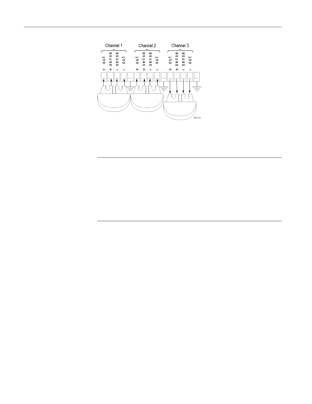
Figure 3: Configuring the shorting clips on a Remote Sense connector to test
channel 3 on a 2230-30-1
3. Set up the equipment as shown. (See Figure 4.)
NOTE. To assure accurate measurements, it is important that a significant amount
of current does not flow through the sense leads. For this reason, we recommend
that the wiring o f the remote sense and the voltmeter be away from the high
curren
t connections between the electronic load and the DUT.
A solution is a pair fork lugs with all three wires crimped in. Another alternative
is a fo
rk lug between the DUT and the load, and separate connections (probably
also fork lugs) holding the wiring for one or both of the voltmeter and remote
sense. A third alternative is to stack banana jacks at the voltmeter, with the remote
sense toward the voltmeter, and the two high current connections on the outside.
28 Series 2200 Multichannel Programmable DC Power Supplies Technical Reference

 Loading...


