3: General operation Model 3762 10-Channel High Voltage Multiplexer Card
3-2 3762-900-01 Rev. A / July 2017
Follow these recommendations before and after applying power to the equipment:
1. Do not exceed the 3762 maximum voltage as defined in the specifications.
2. Do not exceed the 3762 maximum common mode voltage of 1000 V as defined in the
specifications. Exercise extreme caution when a shock hazard is present at the terminals. The
American National Standard Institute (ANSI) states that a shock hazard exists when voltage
levels greater than 30 V
rms
or 42.4 V peak are present.
3. Make sure the system switch mainframe is grounded through an earth grounded receptacle
before operation.
4. Turn off all power supplies and discharge any stored energy before installing or removing the
3762 from the system switch mainframe or the 3762 wires from the terminals.
5. Inspect all test lead connections for wear and defects such as cracks and exposed wires. Correct
any defect found before operating the instrument.
6. Use appropriately rated cables when switching high voltages.
7. Ensure that the wire clamp at the rear of the card is securely installed.
8. Ensure that the mounting screws for the card are securely connected to the system switch
mainframe chassis in order to provide the proper chassis protective grounding.
9. Read this manual carefully and adhere to all of the safety precautions listed before operating the
instrument.
Wire selection and preparation
The internal wire conductor must be exposed (stripped) to the proper dimensions ensuring correct
insertion depth in the screw terminal conductor. Excessive conductor length will expose electrical
shock hazards to equipment and personnel. If the strip length is too short improper termination will
result, due to the lack of electrical conductive surface area making contact with the screw terminal
conductor.
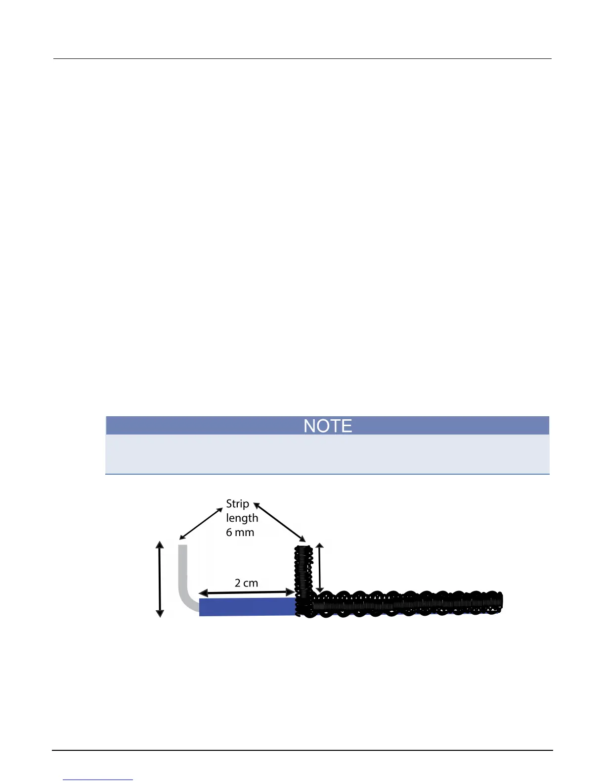
Strip wires to be inserted to six millimeters length, separate all wires by a minimum of one centimeter
if connecting to High and Guard, or if connecting to High and Low, by a minimum of two centimeters.
For example, the next figure is an example of the required distance between High and Low (2 cm).
Figure 4: Strip wire example
The wire must be inserted into the wire hole until the insulation is even with the housing at the wire
hole opening. The screw must be hand tightened with the proper screwdriver to within 0.5 Newton
meter (Nm) screw torque. Once tightened, pull back on the wire to make sure it is secure and make
sure that there are no wire strands outside of the terminal block.

 Loading...


