10-Channel High Voltage Multiplexer Card User's Manual Section 4:
3762-900-01 Rev. A / July 2017 4-3
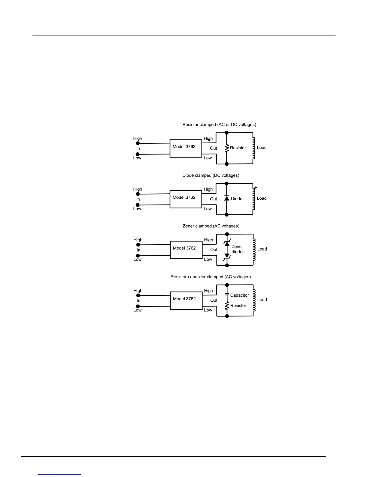
Inductive loads
Inductive reaction voltage, L(di/dt), must be less than 1000 V. Typical clamping circuits are shown in
the next figures. Also, consider the maximum load of 10 VA when determining the voltage limit. For
example, when switching 40 mA, the voltage must be limited to 250 V (V = 10 VA/40 mA) and the
clamping resistor calculation in the next figure would be:
R = V/I = 250 V/40 mA = 6.25 kΩ
Figure 7: Model 3762 Limiting inductive reaction voltage
Make a modification
The guard for channels on the 3762 high voltage multiplexer card are all connected to a common
guard path. If isolation of the guard is required between a channel to any other channel or the output,
the 3762 can be modified to disconnect the guard. The modification involves removing a jumper for
the channel that is to be modified. For example, remove jumper R201 to disconnect channel one's
guard terminal from all other channel output guard terminals.
It is recommended to remove the jumpers by cutting them with a pair of wire cutters.

 Loading...


