Card Connections & Installation
3-5
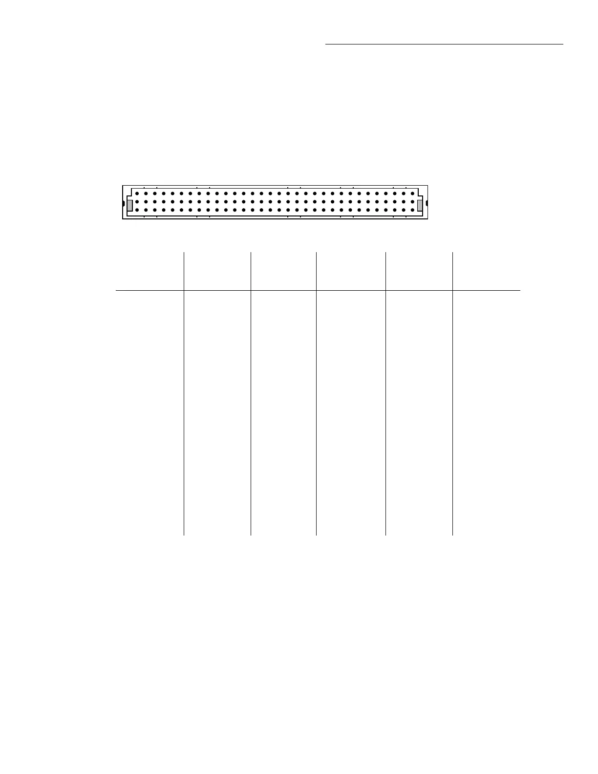
Pins of the Model 7012-C mass termination connector can be identified in one of three ways:
1. Matrix row (1-4) or column (1-10).
2. Connector designation, consisting of rows a-c and columns 1-32.
3. Schematic and component layout designation (1-96).
The following pinout diagrams show the correspondence between these arrangements:
Notes:
1. Refer to the schematic for shield pins.
2. Short pins 1a to 1b on the mating connector (pins 1 and 33 on schematic) to allow the output relays on the con-
nector card to close.
Matrix
Terminal
Connector
Desig.
1a-32c
Schematic
Desig.
1-96
Matrix
Terminal
Connector
Desig.
1a-32c
Schematic
Desig.
1-96
Row 1 HI
LO
8c
8b
72
40
Col 1 HI
LO
32c
32b
96
64
Row 2 HI
LO
6c
6b
70
38
Col 2 HI
LO
30c
30b
94
62
Row 3 HI
LO
4c
4b
68
36
Col 3 HI
LO
28c
28b
92
60
Row 4 HI
LO
2c
2b
66
34
Col 4 HI
LO
26c
26b
90
58
Col 5 HI
LO
24c
24b
88
56
Col 6 HI
LO
22c
22b
86
54
Col 7 HI
LO
20c
20b
84
52
Col 8 HI
LO
18c
18b
82
50
Col 9 HI
LO
16c
16b
80
48
Col 10 HI
LO
14c
14b
78
46
View from pin side
of connector
3231302928272625242322212019181716151413121110987654321
a
b
c
Figure 3-5
Multi-pin connector card terminal identification
Artisan Scientific - Quality Instrumentation ... Guaranteed | (888) 88-SOURCE | www.artisan-scientific.com
 Loading...


