PARTS, TOOLS, MATERIALS
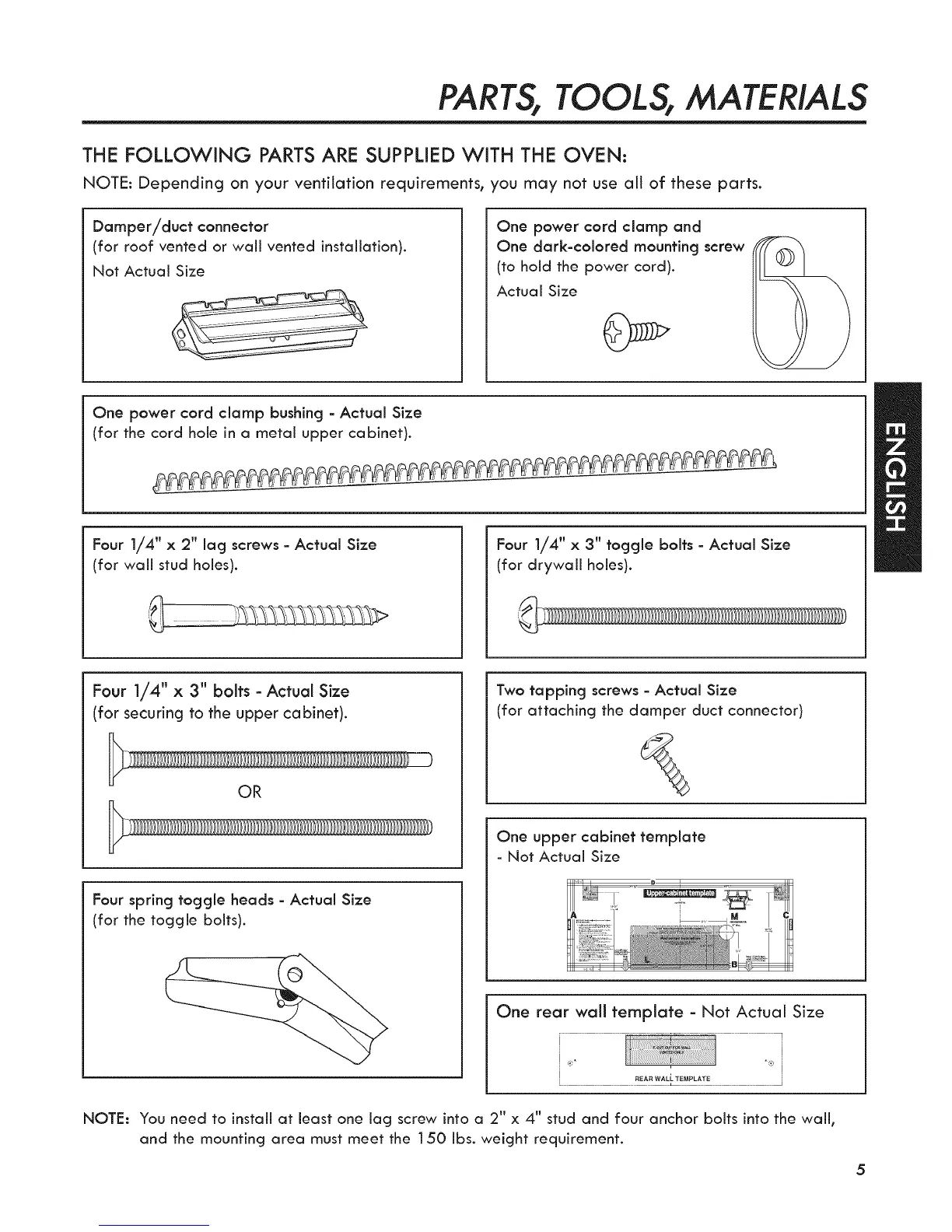
THE FOLLOWING PARTS ARE SUPPLIED WiTH THE OVEN:
NOTE: Depending on your ventilation requirements, you may not use all of these parts.
Damper/duct connector
(for roof vented or wall vented installation).
Not Actual Size
One power cord clamp and
One dark-colored mounting screw
(to hold the power cord).
Actual Size
One power cord clamp bushing - Actual Size
(for the cord hole in a metal upper cabinet).
Four 1/4" x 2" lag screws - Actual Size
(for wall stud holes).
Four 1/4" x 3" toggle bolts - Actual Size
(for drywall holes).
Four 1/4" x 3" bolts - Actual Size
(for securing to the upper cabinet).
OR
Four spring toggle heads - Actual Size
(for the toggle bolts).
Two tapping screws - Actual Size
(for attaching the damper duct connector)
One upper cabinet template
- Not Actual Size
One rear wall template - Not Actual Size
i
!
NOTE: You need to install at least one lag screw into a 2" x 4" stud and four anchor bolts into the wall,
and the mounting area must meet the 150 Ibs. weight requirement.
5
 Loading...