EasyManuals Logo

Kenwood KR-6030 Service Manual

Kenwood KR-6030
18 pages
To Next Page IconTo Next Page
To Previous Page IconTo Previous Page
Page #7 background imageLoading...
Page #7 background image
4
i
CIRCUIT
DESCRIPTION
DC
DETECTION
The
relay
is
released
when
DC
voltage
appears
at
the
out-
put
terminals.
Thus
the
loudspeaker
system
can
be
protect-
ed.
When
positive
(+}
potential
is
generated
at
the
output
terminals,
Qe19
is
turned
on
to
turn
off
Qe21
and
Qe22,
and
the
relay
is
released.
When
negative
(—)
potential
appears
at
the
output
terminals,
Qe18
is
turned
on
to
turn
on
Qe20.
This
causes
Oe21
and
Qe22
to
turn
off,
and
the
relay
to
be
released.
MUTING
OPERATION
FOR
AM
+Vcc
Relay
AM
signal
line
Signal
short-
circuited
to
GND)
Transistor
Qg6
composes
an
AM
muting
circuit.
When
the
selector
switch,
Sg1,
is
set
in
the
FM
position,
+14
V
is
applied
to
the
anode
of
Dg3.
Then
voltage
is
applied
to.the
base
of
Qg6
to
turn
it
on.
The
AM
signal
is
transferred
to
the
GND
circuit
and
the
tuner
output
cannot
be
fed
to
the
preamplifier.
In
the
AM
position,
voltage
to
the
base
is
applied
from
the
—50
V
and
Og
6
is
turned
off.
The
signal
is
then
fed
to
the
preamplifier.
When
the
power
switch,
S1,
is
turned
off
while
the
selector
switch
is
in
the
AM
position,
there
may
be
a
signal
leakage.
To
avoid
it,
the
AM
signal
is
transferred
to
the
GND
circuit
simultaneously
when
the
power
switch
is
turned
off.
When
the
power
switch
is
off,
the
relay
driving
transistor
Qe21
is
also
off
and
the
collector
potential
is
raised
as
a
result.
This
potential
is
applied
to
the
base
of
Qg6
through
Rg82,
and
the
AM
signal
is
led
to
the
GND
circuit
as
described
previously.
MUTING
OPERATION
FOR
FM
+14V
during
+18V
the
FM
position
|
+B
for
the
FM
|
front
end
circuit
I
and
ICg3
\Cg1
Rg78
No.
12
terminal
Dgs
12
(switch)
Y
\cg3
Qg
'
No.
10
ICg3
terminal
No.
11
terminal
Qg8
|
Qg9
|0g10]
Qg12
(switch)
short-circuit
The
schematic
is
an
FM
muting
circuit,
which
is
controlled
by
No.
12
terminal
voltage
of
IC
HA1137W.
Voltage
at
No.
12
terminal
is
0
volt
during
tuning
and
0.8
volt
during
detuning.
When
Qg8
is
turned
off,
+B
is
applied
to
No.
11
terminal
of
ICg3
to
stop
the
stereo
operation.
Qg10
is
turned
on
a
few
seconds
after
switching
over
from
the
other
function
to
FM.
This
is
controlled
by
a
delay
circuit.
During
tuning
During
detuning

Questions and Answers:

Question and Answer IconNeed help?

Do you have a question about the Kenwood KR-6030 and is the answer not in the manual?
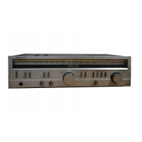
Kenwood KR-6030 Specifications

Amplifier Section IconAmplifier Section
power output80 watts per channel
total harmonic distortion0.1% at rated power into 8 ohms
intermodulation distortion0.1% at rated power into 8 ohms
Power IconPower
power consumption600 W at full power
dynamic power output340 W
maximum input level for phono250 mV (RMS), T.H.D. 0.1% at 1, 000 Hz
Weight and Dimensions IconWeight and Dimensions
weight30.9 lbs (14.0 kg)
gross weight35.2 lbs (16.0 kg)
dimensionsW 18-29/32" (480 mm), H 5-7/8" (149 mm), D 15-15/16" (405 mm)

Related product manuals