4
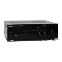
KRF-V5200D
CIRCUIT DESCRIPTION
●
Fan Motor Control
Fan control signal from the microprocessor IC601 (X08)
is supplied to the base of the transistor Q502 if changes
thermal level. Normally the base voltage of Q502 is low and
Q502 is not turn-on. The base of Q503 is minus voltage
so Q503 is turn-on. Zener diodes D512 and 513 are short
circuitry if Q503 is on. The collector’s voltage of Q503 will be
the same as zener diode D524, -10volts. This voltage leads
fan motor to turn with low speed.
●
AK4586VQP (IC401: X08) Port Description
Pin No. Pin Name I/O Description
1 XTO OUT Crystal output port
2 XTI IN Crystal input port
3 DVDD - Power supply for digital circuit (4.5 to 5.5V)
4 DVSS - Ground for digital circuit
5 TVDD - Buffer of power supply (2.7 to 5.5V)
6 TX OUT Transmit channel (though data) output port.
7 MCKO OUT Master clock output port
8 LRCK IN/OUT Input/output channel clock port
9 BICK IN/OUT Audio serial data clock port
10 SDTO OUT Audio serial data output port
11 SDTI1 IN DAC1 audio serial data input port
12 SDTI2 IN DAC2 audio serial data input port
13 SDTI3 IN DAC3 audio serial data input port
14 INT0 OUT Interrupt 0 port
15 INT1 OUT Interrupt 1 port
16 CDTO OUT Control data output port for 4-serial control mode
17 CDTI IN Control data input port for 4-serial control mode
18 CCLK IN Control data clock port for 4-serial control mode
19 CSN IN Chip selector port for 4-serial control mode
20 DZF2 OUT Zero detector input port-2.
21 AVSS - Ground for analog circuit
22 AVDD - Power supply for analog circuit (4.5 to 5.5V)
23 VREFH IN Reference voltage port, AVDD
24 VCOM OUT Common voltage port, AVDD/2
25 DZF1 OUT Zero detector input port-1.
26 LOUT3 OUT L-ch analog output port from internal DAC3
27 ROUT3 OUT R-ch analog output port from internal DAC3
28 LOUT2 OUT L-ch analog output port from internal DAC2
29 ROUT2 OUT R-ch analog output port from internal DAC2
30 LOUT1 OUT L-ch analog output port from internal DAC1
When thermal sensor works, the microprocessor will send
the signal to Q502 and Q502 is turn-on. The base of Q503
becomes high level and it is not turn-on. Zener diodes D512
and 513 work. The base of Q504 is high level, -26volts. Fan
motor will turn with high speed.
 Loading...
