45
INTERFACING TO PERIPHERALS
SP/MIC JACK
The SP/MIC jack on the transceiver can be
configured to interface to various kind of the
peripherals available for the transceiver, such as a
speaker microphone (SMC-32/ 33/ 34), PC interface
cable and a TNC. Access Menu No. 9 (SP/MIC
JACK) and select the peripheral type from “SP/MIC”,
“TNC”, and “PC”.
You can further configure the transceiver to interface
to a high speed (9600 bps) TNC that requires a direct
FM modulation {below}.
SELECTING SP/MIC JACK FUNCTION
Unless you connect the transceiver to a TNC or PC,
the default setting of the SP/MIC jack function (Menu
No. 9), “SP/MIC” works fine. However, if you want to
interface to a different type of peripheral, configure
the SP/MIC jack function:
1 Press [MNU] to enter Menu mode.
2 Turn the Tuning control or press [ ]/ [ ] to select
Menu No. 9 (SP/MIC JACK).
3 Press [ ] or [MNU].
4 Turn the Tuning control or press [ ]/ [ ] to select
the appropriate peripheral type from “SP/MIC”
(default), “TNC”, and “PC”.
CIM/PS
noitcnuF
epyTlarehpireP
CIM/PS
,tesdaeh,enohorcimrekaepS
hcleuqsatuohtiwCNT,enohprae
troppussutats
CNTtroppussutatshcleuqsahtiwCNT
CP
lortnoclennahcyromemehthtiwCP
reviecsnartehtroferawtfos
5 Press [ ] or [MNU] to store the setting.
Otherwise, press [ ] or [PTT] to cancel.
• If necessary, configure and select the
additional settings.
6 Press [ ] (POWER) to turn the transceiver OFF.
7 Connect a peripheral to the SP/MIC jack.
8 Press [ ] (POWER) to turn the transceiver ON.
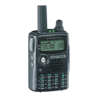
■ SP/MIC
If you plug the speaker microphone or headset
into the SP/MIC jack, access Menu No. 9 and
select “SP/MIC” (default). To emulate the
programmable function keys using external keys
in order to control the transceiver, refer to the
circuit diagram below {page 38}.
3.5 V
10 µF
PTT
LOCK SW
SW-1 3.9k
SW-2 10k
SW-3 27k
TH-F6A/ TH-F7E
SP
MIC
Note 1:
Voltage is developed across a 100
Ω
resistor on the 3.5 V line in
the transceiver. When 2 mA flows, approximately 3.3 V is
developed.
Note 2:
A 10
µ
F capacitor is not required in the following cases.
•
When other equipment has DC blocking capacitors.
•
When a 2-terminal electret condenser microphone is used.
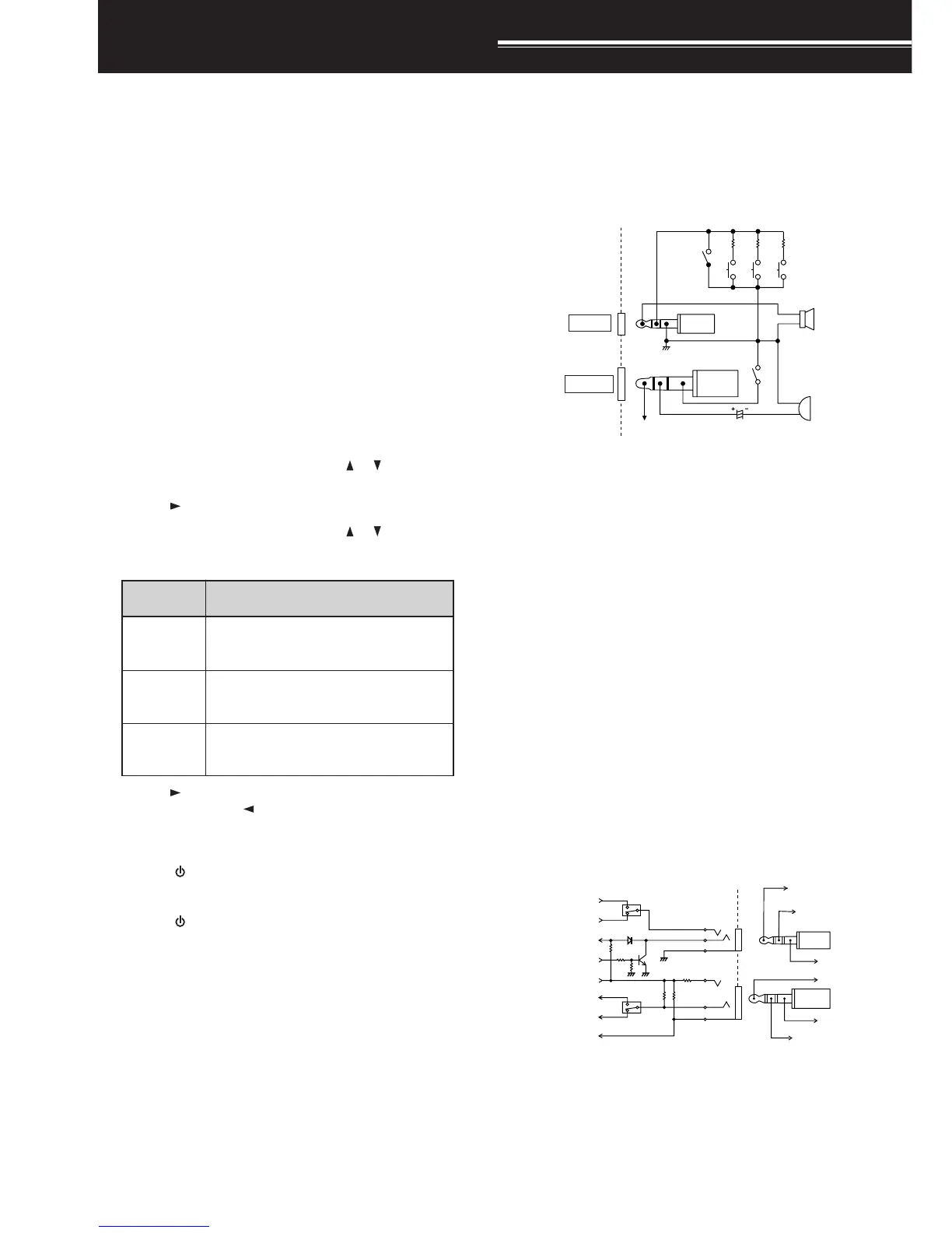
■ TNC
If you want to utilize the squelch status on your
TNC, access Menu No. 9 and select “TNC”. From
the TNC, make the interface cable that connects
to SP/PRD, MIC/PKD, PTT, REM/SQ, and GND
on the transceiver SP/MIC jack terminal. In
addition, if your TNC supports 9600 bps packet
(G3RUH/ GMSK 9600 bps modem), access Menu
No. 28 (PACKET) and select “9600” bps. This
option allows you to transmit/ receive packet
signals in a direct FM modulation/ quadrature
detector output. You must use the A-band to
transmit and receive 9600 bps packet signal.
The following diagram shows the available
terminals on the SP/MIC jack for the TNC.
 Loading...