TK-2312/2317
29
ADJUSTMENT
Test Equipment Required for Alignment
Test Equipment Major Specifi cations
1. Standard Signal Generator (SSG)
Frequency Range 136 to 174MHz
Modulation Frequency modulation and external modulation
Output –127dBm/0.1µV to greater than –47dBm/1mV
2. RF Power Meter
Input Impedance 50
Ω
Operation Frequency 136 to 174MHz
Measurement Range Vicinity of 10W
3. Deviation Meter Frequency Range 136 to 174MHz
4. Digital Volt Meter (DVM)
Measuring Range 10mV to 10V DC
Input Impedance High input impedance for minimum circuit loading
5. Oscilloscope DC through 30MHz
6. High Sensitivity
Frequency Counter
Frequency Range 10Hz to 1000MHz
Frequency Stability 0.2ppm or less
7. DC Ammeter 5A
8. AF Volt Meter (AF VTVM)
Frequency Range 50Hz to 10kHz
Voltage Range 1mV to 10V
9. Audio Generator (AG)
Frequency Range 50Hz to 5kHz or more
Output 0 to 1V
10. Distortion Meter
Capability 3% or less at 1kHz
Input Level 50mV to 10Vrms
11. Spectrum Analyzer Measuring Range DC to 1GHz or more
12. Tracking Generator
Center frequency 50kHz to 600MHz
Output Voltage 100mV or more
13. 8
Ω
Dummy Load Approx. 8
Ω
, 3W
14. Regulated Power Supply
5V to 10V, approx. 3A
Useful if ammeter equipped
■
Antenna connector adapter
The antenna connector of this transceiver uses an SMA
terminal.
Use an antenna connector adapter [SMA(f) – BNC(f) or
SMA(f) – N(f)] for adjustment. (The adapter is not provided
as an option, so buy a commercially-available one.)
■
Repair Jig (Chassis)
Use jig (part No.: A10-4215-03) for repairing the trans-
ceiver. Place the TX-RX unit on the jig and fi t it with screws.
The jig facilitates the voltage check and protects the fi nal
amplifi er FET when the voltage on the fl ow side of the TX-
RX unit is checked during repairs.
■
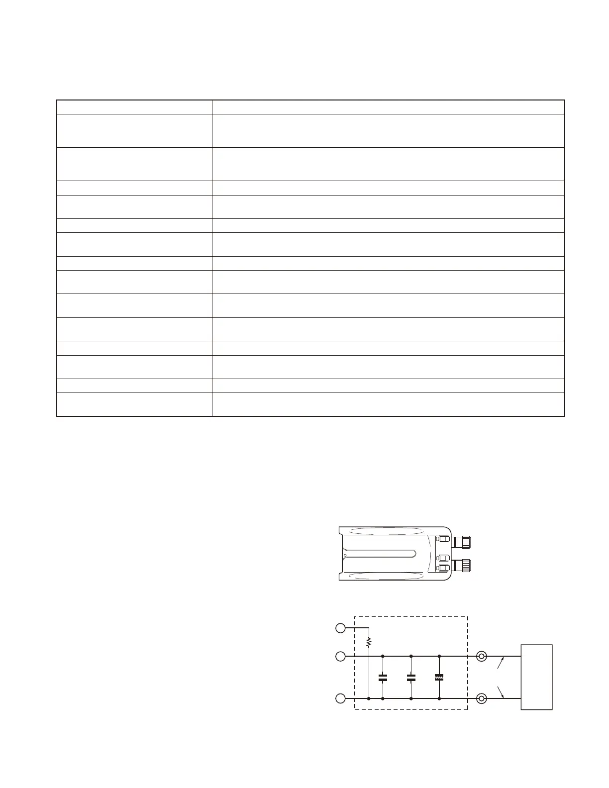
Battery Jig (W05-1011-00)
Connect the power cable properly between the battery
jig installed in the transceiver and the power supply, and
be sure output voltage and the power supply polarity prior
to switching the power supply ON, otherwise over voltage
and reverse connection may damage the transceiver, or the
power supply or both.
Note: When using the battery jig, you must measure the
voltage at the terminals of the battery jig. Otherwise, a
slight voltage drop may occur within the power cable, be-
tween the power supply and the battery jig, especially while
the transceiver transmits.
+ Terminal (Red)
– Terminal (Black)
S
–
+
C1
100P/25V
C2
470P/25V
C3
100/25V
R1
1.8M
+
+Terminal
(Red)
–Terminal
(Black)
Power
supply
Power
cable
Schematic diagram

 Loading...