TK-8302/8302H
10
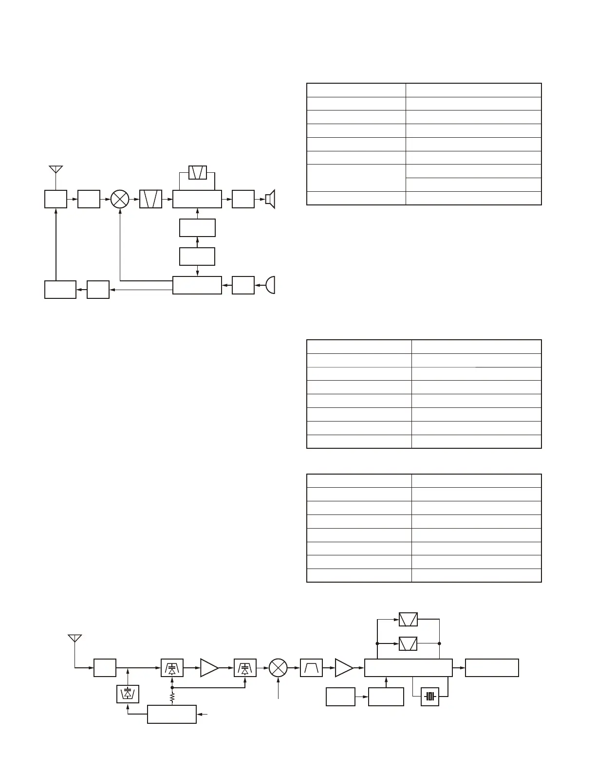
1. Frequency Confi guration
The receiver utilizes double conversion. The first IF is
38.85MHz and the second IF is 450kHz. The fi rst local oscil-
lator signal is supplied from the PLL circuit.
The PLL circuit in the transmitter generates the neces-
sary frequencies. Figure 1 shows the frequencies.
ANT
SW
RF
AMP
1st
MIX
AF
PA
TCXO
MIC
AMP
X2
multiply
RF
AMP
POWER
AMP
CF 450kHz
MCF
38.85MHz
IF SYSTEM
PLL/VCO
19.2MHz
38.4MHz
ANT
RX
TX
SP
MIC
Fig. 1 Frequency confi guration
2. Receiver System
The receiver is a double conversion superheterodyne.
The frequency confi guration is shown in Figure 1.
2-1. Front-end RF Amplifi er
An incoming signal from the antenna is applied to an RF
amplifier (Q506) after passing through a transmit/receive
switch circuit (D302, D303, D304 and D305), BPF (L517,
L518 and varactor diodes: D509, D510) and the Notch fi lter
(L519 and varactor diode: D511). The Notch fi lter function is
to eliminate the image frequency.
After the signal is amplifi ed (Q506), the signal is fi ltered
by a BPF (L511, L512, L513 and varactor diodes : D505,
D506, D508) to eliminate unwanted signals before it is
passed to the fi rst mixer.
The voltage of these diodes are controlled by tracking
the MCU (IC702) center frequency of the bandpass filter.
(See Figure 2)
2-2. First Mixer
The signal from the RF amplifi er is heterodyned with the
fi rst local oscillator signal from the PLL frequency synthe-
sizer circuit at the fi rst mixer (Q504) to create a 38.85MHz
fi rst intermediate frequency (1st IF) signal. The fi rst IF signal
is then fed through one pair of monolithic crystal fi lters (MCF:
XF500) to further remove spurious signals.
Item Rating
Nominal center frequency 38.85MHz
Pass bandwidth ±6.0kHz or more at 3dB
40dB stop bandwidth ±25.0kHz or less
Ripple 1.0dB or less
Insertion loss 4.0dB or less
Guaranteed attenuation
75dB (–900kHz); 50dB (+900kHz)
Spurious: 40dB or more within fo±1MHz
Terminal impedance 610
Ω
// 3.0pF// Coupling Cap 13.0pF
Table 1 Crystal fi lter (L71-0659-05): XF500
2-3. IF Amplifi er Circuit
The fi rst IF signal is amplifi ed by Q502, and enters IC500
(FM processing IC). The signal is heterodyned again with
a second local oscillator signal within IC500 to create a
450kHz second IF signal. The second IF signal is then fed
through a 450kHz ceramic filter (Wide: CF500, Narrow:
CF501) to further eliminate unwanted signals before it is
amplifi ed and demodulated by the quadrature detector with
the ceramic discriminator (CD500).
Item Rating
Nominal center frequency 450kHz
6dB bandwidth ±6.0kHz or more
50dB bandwidth ±12.5kHz or less
Ripple 2.0dB or less
Insertion loss 6.0dB or less
Guaranteed attenuation 35.0dB or more within fo±100kHz
Terminal impedance 2.0k
Ω
Table 2 Ceramic fi lter (L72-0993-05): CF500
Item Rating
Nominal center frequency 450kHz
6dB bandwidth ±4.5kHz or more
50dB bandwidth ±10.0kHz or less
Ripple 2.0dB or less
Insertion loss 6.0dB or less
Guaranteed attenuation 55.0dB or more within fo±100kHz
Terminal impedance 2.0k
Ω
Table 3 Ceramic fi lter (L72-0959-05): CF501
CIRCUIT DESCRIPTION
Fig. 2 Receiver System
ANT
L517,L518
D509,D510
BPF
Q506
RF AMP
Q502
IF AMP
Q504
MIX
XF500
MCF
D302,D303
D304,D305
ANT
SW
IC501
DC OP AMP
Q500
Doubler
X1
TCXO
IC500
FM IC system
IC701
Baseband IC
1st local
OSC (VCO/PLL)
CF500 (Wide)
CF501 (Narrow)
TV
CD500
TVC &
APCC
D511, L519
Notch filter
L513,L512,L511
D508,D506
D505
BPF
 Loading...