37
Structural Features
●
Internal structure of the main unit
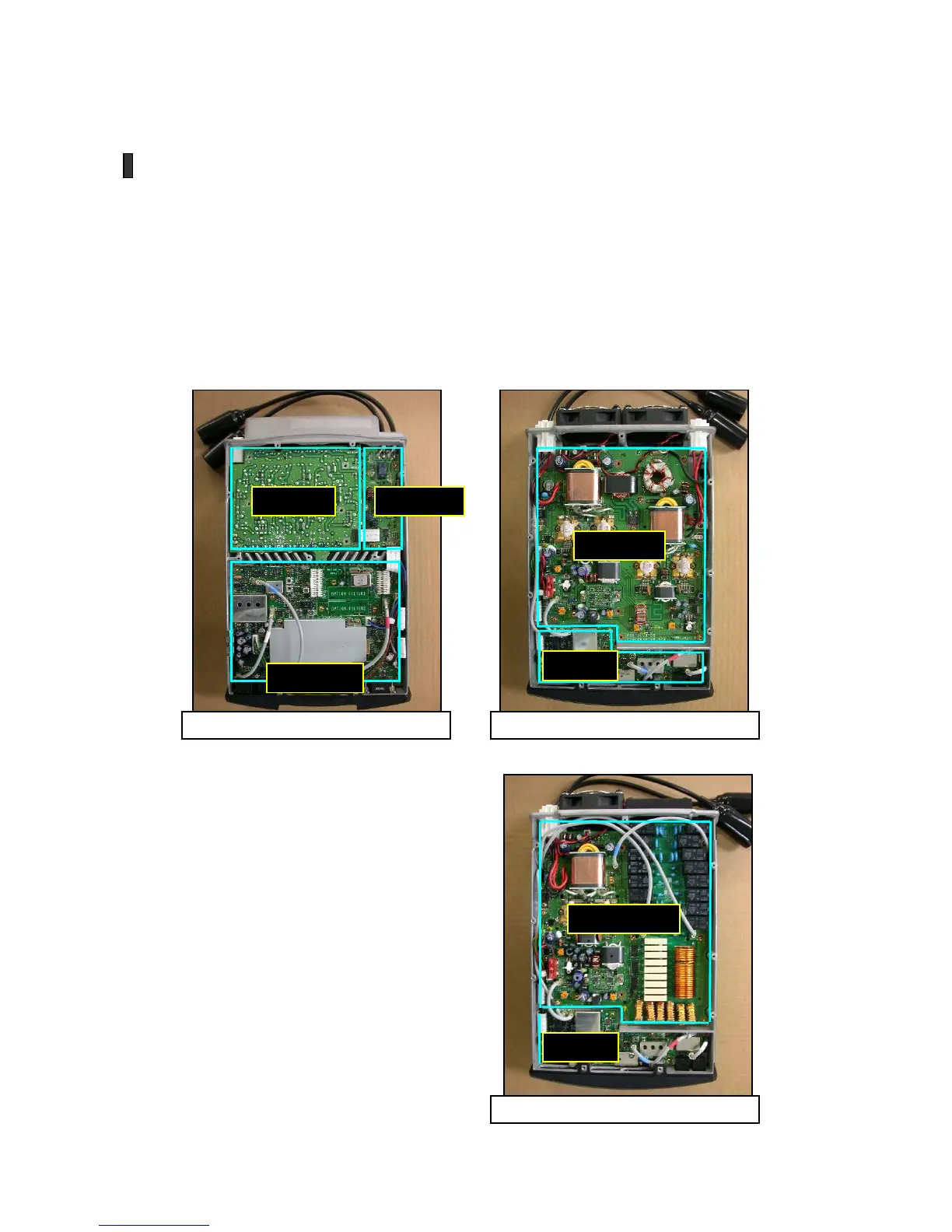
The internal structure of the main unit is straightforward: employing a die-cast aluminum chassis, it
is designed so that the circuit boards are attached from both above and below. From above one
can see the TX/RX unit, the filter unit and the relay unit; seen from below, there are the RF unit and
the final unit (or final/AT unit, in the case of the SAT model). There is also a separate display unit in
the standalone control panel.
Figs. 23~25 illustrate the arrangement of these units.
Filter unit
Rela
unit
TX /RX unit
Final unit
RF unit
Final /AT unit
RF unit
Fig.23
: View from above (both models)
Fig.24
: View from below (TS-480HX)
Fig.25
: View from below (TS-480SAT)

 Loading...