9
EN
The LED ashing light must be connected to the COM and FLASH
terminals.
The courtesy light must be connected to the COM and LED termi-
nals.
The SBS step by step contact must be connected to the COM and
SBS terminals (normally open NO contact).
The photocell contact must be connected to the COM and PH ter-
minals. To bypass the photocell, move the left-hand dip switch
upwards. After having activated the dip switch, the LEDs L1
and L2 start to ash at a fast rate.
CONFIRM INPUT PH DEACTIVATION BY PRESSING THE MENU
AND RADIO BUTTONS SIMULTANEOUSLY AND HOLDING
THEM DOWN UNTIL THE LEDs L1 AND L2 STOP FLASHING.
The inputs of the sensitive EDGE must be connected to the EDGE
and EDGE terminals. To bypass the sensitive edge, move the
right-hand dip switch upwards. After having activated the dip
switch, the LEDs L1 and L2 start to ash at a fast rate.
CONFIRM INPUT EDGE DEACTIVATION BY PRESSING THE
MENU AND RADIO BUTTONS SIMULTANEOUSLY AND HOLD-
ING THEM DOWN UNTIL THE LEDs L1 AND L2 STOP FLASH-
ING.
ATTENTION !
ATTENTION !
SBS
STEP BY STEP NO contact control between SBS and COM
Open/Stop/Close/Stop control or control based on software selection
STOP
NO contact STOP between STOP and COM. The contact can be activated at any time and will immediately lock the
automation system, disabling any function including automatic closing
COM SBS, STOP input common
L1 RED LED indicating programming of control panel parameters
MENU Key for programming control panel parameters
RADIO Key for programming integrated radio parameters
L2 GREEN LED indicating programming of radio parameters
KUBE/DYL DYL and KUBE connector
SBS SBS (STEP-BY-STEP) key for automation system control
DIP1/PH
DIP2/EDGE
Dip switch for disabling safety devices (PH, EDGE) see FIG. 48
SHIELD Antenna - sheath -
ANT Antenna - signal -
4.11 - Memorising a remote control
If you have a KUBE PRO wireless module, connect it to the control
unit (FIG. 49, 50) and follow the instructions on the screen.
If you have a DYL cable module, connect it to the control unit and
MEMORISING A REMOTE CONTROL
By activating the memorising phase any transmitter within the
range can be stored. To reduce the receiver range, disconnect
ATTENTION !
follow the instructions on the screen.
Otherwise proceed as described below:
the antenna temporarily.
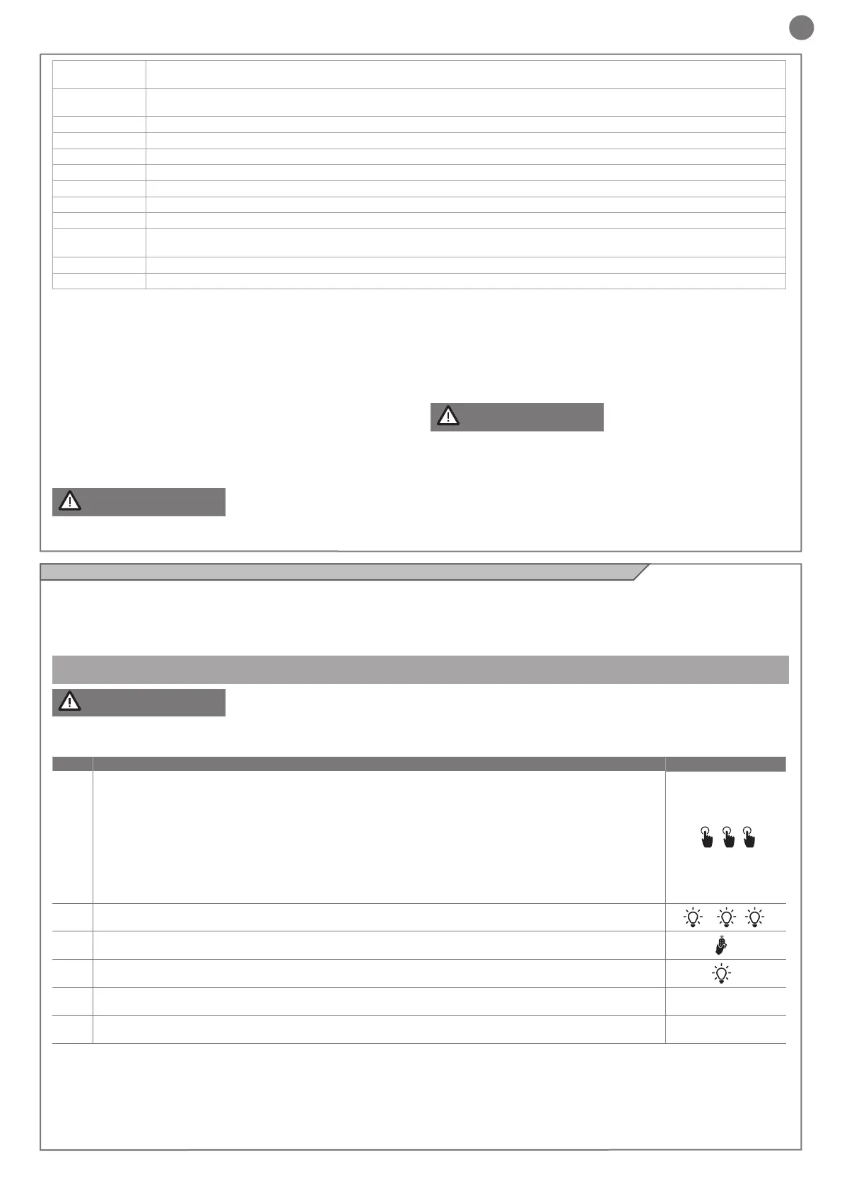
PHASE DESCRIPTION
EXAMPLE
1
Press and release the RADIO button for a number of times equal to the feature that you wish to activate:
1 time for the feature: SBS (STEP-BY-STEP or OPEN - STOP - CLOSE - STOP),
2 times for the feature: PARTIAL OPENING,
3 times for the feature: OPENING ONLY,
4 times for the feature: LIGHT ON/OFF,
5 times for the feature: PRE-SET (key 1 = SBS, key 2 = PARTIAL OPENING, key 3 = OPENING ONLY,
key 4 = LIGHT ON/OFF)
6 times for the feature: WALL BUTTON (key 1 = CLOSES/STOP, key 2 = OPENS/STOP,
key 3 = VENTILATION, key 4 = LIGHT ON/OFF)
+ +
2 LED L2 ashes a number of times corresponding to the selected output at 1 second intervals
1s► 1s►
3 Within 10 seconds, press and hold the button of the radio control that you wish to store for at least 2 seconds
>2s
4 If the memorisation has been successful, the LED L2 will emit a long ash
>3s
5 To memorize another remote control on the same output, repeat point 3
Note After 10 seconds of inactivity, the receiver automatically exits the programming phase
 Loading...