TP-6073 4/06 33Section 6 Controller Troubleshooting
6.2 Controller Circuit Board
It is possible to check some controller circuit board
components (relays) without removing them from the
board. Check these relays before installing a new board
and attempting startup. Use a high quality multimeter
and follow the manufacturer’s instructions. To obtain
accurate readings when testing, remove all the circuit
board connectors and conformal coating (transparent
insulation) from the component terminals. Use the chart
in Figure 6-2
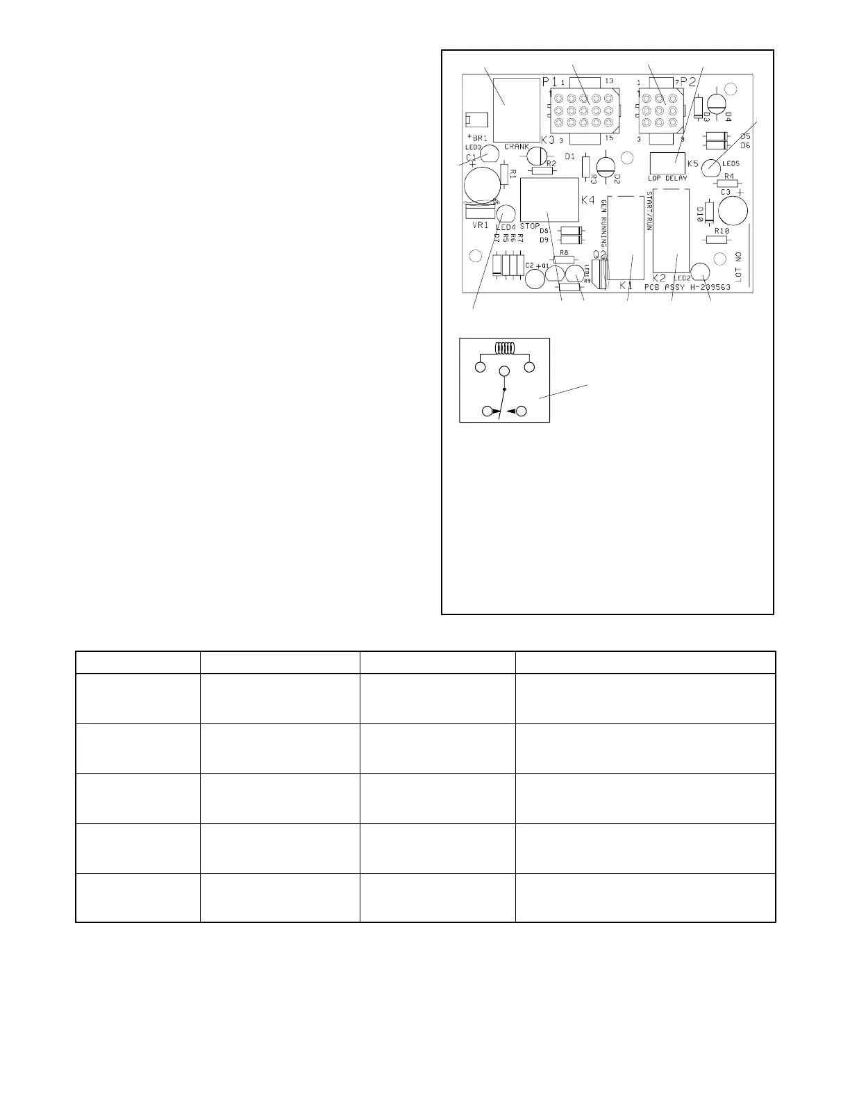
The controller circuit board has LEDs to indicate the
presence of relay coil power and aid in circuit board and
generator fault detection. See Figure 6-1. When the
K1-K5 relays energize, the corresponding LEDs light.
The LEDs do not indicate whether the relay coil is
functional or not. This conclusion can only be reached
through analyzing the fault.
H-239563
1
4
5
6
7
8
910
12
13
23
11
1. Engine crank control relay (K3)
2. P1 connector
3. P2 connector
4. Time delay relay (K5)
5. LED5
6. LED2
7. Engine run relay (K2)
8. AC crank disconnect relay (K1)
9. LED1
10. Fault shutdown relay (K4)
11. Relay schematic
12. LED4
13. LED3
Figure 6-1 Controller Circuit Board H-239563
Component Ohmmeter Connections Procedure Results
K1 Relay Coil K1 coil terminals
(see relay schematic)
OhmmeteronRx10
scale
If functional, approximately 270 ohms.
Low resistance (continuity), shorted coil.
High resistance, open coil.
K2 Relay Coil K2 coil terminals
(see relay schematic)
OhmmeteronRx10
scale
If functional, approximately 270 ohms.
Low resistance (continuity), shorted coil.
High resistance, open coil.
K3 Relay Coil K3 coil terminals
(see relay schematic)
OhmmeteronRx10
scale
If functional, approximately 400 ohms.
Low resistance (continuity), shorted coil.
High resistance, open coil.
K4 Relay Coil K4 coil terminals
(see relay schematic)
OhmmeteronRx10
scale
If functional, approximately 125 ohms.
Low resistance (continuity), shorted coil.
High resistance, open coil.
K5 Relay Coil K5 coil terminals
(see relay schematic)
OhmmeteronRx10
scale
If functional, approximately 510 ohms.
Low resistance (continuity), shorted coil.
High resistance, open coil.
Figure 6-2 Relay Testing
 Loading...

