TP-6073 4/06 53Section 8 Component Troubleshooting
8.2 Remote Start Panels (Optional)
Kohler Co. offers three remote panels. The first has a
start/stop switch. The second has a start/stop switch
and two gauges. The third has a start/stop switch and
four gauges. Test the switch, gauge, and gauge sender
functions if difficulty with remote operation occurs.
Disconnect the J3/P3 connector before testing.
8.2.1 Sender Tests
To test the water temperature sender, connect an
ohmmeter to controller sockets P3-1 and P3-2. See
Figure 8-3 for the resistance generated by different
temperatures. Start the generator set to change
temperature. Stop the generator set after completing
the test.
To test the oil pressure sender, connect an ohmmeter to
controller sockets P3-1 and P3-3. See Figure 8-4 for the
resistances generated by different pressures. Start the
generator set to change pressure. Stop the generator
set after completing the test.
Generally, senders can be presumed functional if they
change their resistance values as their respective
pressure/temperature change.
8.2.2 Panel Tests
Test the panels with an ohmmeter as described in
Figure 8-5 or with a voltmeter as described in
Figure 8-6. Refer to Figure 8-3 and Figure 8-4 for
desired resistance values.
2-Meter and 4-Meter Panels
Temperature Resistance
60_C (140_F)
90_C (194_F)
100_C (212_F)
134.0 ±10 ohms
51.5 ±4 ohms
38.0 ±3 ohms
Figure 8-3 Water Temperature Sender Resistance
2-Meter and 4-Meter Panels
Pressure Resistance
0 kPa (0 psi)
103 kPa (15 psi)
207 kPa (30 psi)
310 kPa (45 psi)
9 ±4 ohms
48 ±4 ohms
84 ±4 ohms
120 ±5 ohms
Figure 8-4 Oil Pressure Sender Resistance
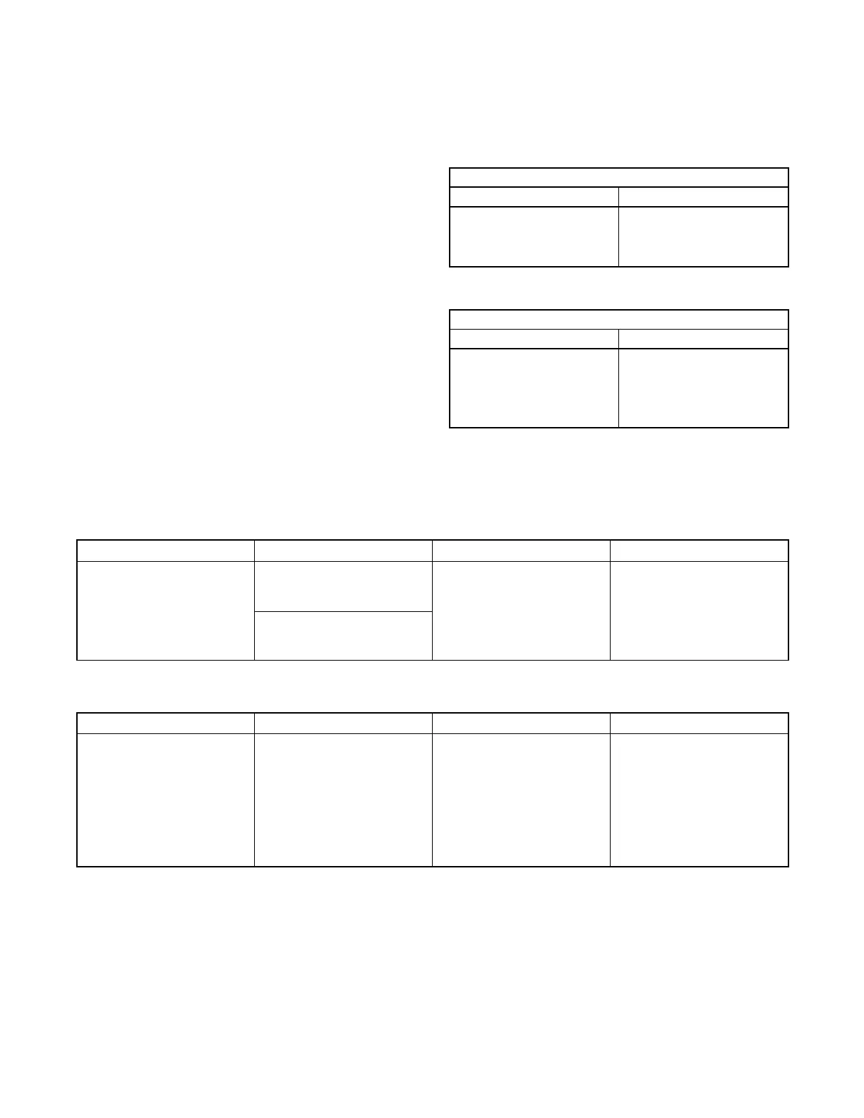
Component Voltmeter Connections Remarks Results
Start/stop switch
P3-1 and P3-5 (plug side).
Place the remote rocker
switch in the START position.
OhmmeteronRx1scale If functional, ohmmeter
indicates continuity.
P3-1 and P3-6 (plug side).
Place the remote rocker
switch in the STOP position.
Figure 8-5 Remote Panel Testing with Ohmmeter
Component Voltmeter Connections Remarks Results
Remote switch “ON” light,
gauge lights, DC voltmeter,
and hourmeter, if equipped
Red test lead to P3-4 (socket
side) and black test to P3-1
(socket side). Place the
controller start/stop switch in
the START position.
STOP the generator set when
the test is completed.
Voltmeter setting 12 volts or
greater. Generator set does
not need to be running, just
cranking for this test.
NOTE: If the hourmeter is not
illuminated connect it to a
12-volt battery.
NOTE: Hourmeter is polarity
sensitive.
If 12 volts DC is present and
the hourmeter does not
function after the P3 plug is
connected to controller,
replace the hourmeter.
Figure 8-6 Remote Panel Testing with Voltmeter
 Loading...

