TP-6073 4/06 57Section 9 Generator Disassembly/Reassembly
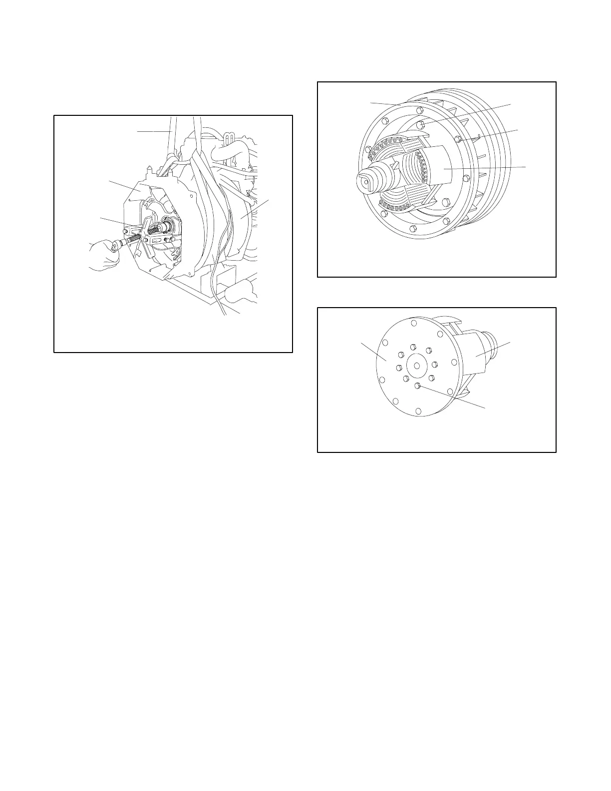
21. Install a sling on the stator housing. See
Figure 9-7.
22. Use a two-jaw puller to pull the end bracket/stator
assembly from the bearing on the rotor shaft. See
Figure 9-7.
558867
1
1. Sling
2. Fan guard
3. Two-jaw puller
4. End bracket
4
2
3
Figure 9-7 Stator Assembly Removal
23. Remove the stator assembly from the rotor.
Remove or rotate the fan guard, if necessary, to
clear the vibromounts.
24. Remove the eight fan bolts and remove the fan and
fan spacer. See Figure 9-8.
25. Remove the eight drive disc bolts to remove the
drive disc/rotor assembly from the engine flywheel.
SeeFigure9-8.
26. Clamp the rotor in a soft-jaw vise. Remove the eight
bolts and remove the drive disc assembly from the
rotor. See Figure 9-9.
558868
1
3
1. Fan
2. Drive disc/rotor bolts
3. Fan bolts
4. Rotor assembly
2
4
Figure 9-8 Disc/Rotor and Fan Assembly
5588610
1
2
3
1. Drive disc
2. Rotor
3. Bolt
Figure 9-9 Drive Disc
 Loading...

